
IP69K Sensors for Washdown: Food, Dairy and Beverage Lines

IP67 and IP69K protect against completely different things, and a sensor can pass one while failing the other. What high-pressure washdown actually does to a sensor, and how to specify for it.

Sensors on food, dairy and beverage lines do not usually fail because of the process. They fail because of the cleaning.

A clean-down cycle can combine water at 80 bar and 80 degrees Celsius with a caustic or acidic detergent, applied at close range by someone whose priority is a clean machine rather than an intact sensor. It is a more aggressive environment than the production process it is protecting, and it defeats hardware specified for the process alone.

IP67 and IP69K protect against different things

This is the distinction that matters, and it is routinely missed because the numbers look sequential.

IP67 certifies protection against temporary immersion — the sensor can sit under water at low pressure for a defined period. It says nothing about pressure, nothing about temperature, and nothing about a directed jet.

IP69K certifies protection against close-range, high-pressure, high-temperature water jets. The test applies water at approximately 80 bar and around 80 degrees Celsius from a short distance, at several angles, while the item rotates.

These are genuinely different failure mechanisms. Immersion applies gentle uniform pressure. A high-pressure hot jet applies concentrated force at a seam, and heat at the same time. Heat causes the air inside a sealed housing to expand and then, as the jet passes and the surface cools rapidly, to contract — creating a partial vacuum that actively draws water past any seal that is less than perfect.

That thermal cycling is why washdown failures often appear weeks after installation rather than immediately, and why a sensor can pass an IP67 test and still fail in a dairy.

Neither rating covers the chemistry

IP ratings test with water. Clean-down uses detergents, and typically alternates caustic and acid cycles. Chemical compatibility is a separate question from ingress protection and needs asking separately.

The materials that matter are the housing, the sensing face, the cable sheath and the seals. Stainless steel housings are standard for good reason; the cable sheath is the component most often overlooked and quite often the first to degrade. If your CIP regime uses a specific detergent, name it when you enquire.

What else to specify beyond the rating

  • Hygienic mounting. Flush mounting with no crevices, no exposed threads collecting product, no horizontal ledges. In many plants this is an audit requirement, not a preference.
  • Cable entry orientation. The most common ingress path is a cable entry pointing upward, collecting standing water. Point it down, or specify a connector version.
  • The connector, if used. An IP69K sensor on an IP65 connector is an IP65 installation. The rating applies to the assembly, not the most impressive component in it.
  • Temperature range including the clean cycle. The process may run at 4 degrees and the wash at 80. Specify against the wash.
  • Cable length. A joint in the cable inside the wash zone is a failure point. Specify the full run to outside the zone.

What we supply for washdown duty

For position measurement in washdown environments, several Novotechnik series are rated to IP69 and are designed for exactly this kind of duty:

  • RFX-6900 — absolute touchless redundant NOVOHALL heavy duty rotary sensor, rated to IP67 and IP69 variants
  • RSX-7900 — absolute non-contacting redundant NOVOHALL heavy duty rotary sensor, also available to IP69
  • IPX-7900 — absolute high-precision potentiometric rotary sensor for harsh operating conditions, available to IP69

These are touchless or sealed designs with no mechanical path into the measuring element, which is the structural reason they survive washdown rather than merely being rated for it.

For proximity switching duty on washdown lines, tell us the clean-down regime — pressure, temperature, detergent and frequency — and we will confirm what we can supply against it. We manufacture inductive, capacitive and photoelectric switches in Mumbai and can advise on the right specification for the wash conditions you actually run, rather than the ones the catalogue assumes.

A note on over-specification

IP69K is not free, and not every sensor on a food line needs it. A sensor inside a control panel, or one mounted above the wash zone and never directly jetted, does not. Map the wash zone honestly and specify IP69K where the jet actually reaches. Spending the budget on the sensors that get hit, rather than spreading it across all of them, usually produces a more reliable line.

Our overview of IP67, IP68 and IP69K ratings explains what each test involves in more detail.

Need a price, a drawing or a stock check?

Send us the part number, or just describe the application and the target you need to sense. We will come back with the right model, a dimensional drawing and a quotation. Accent Controls has built sensors in Mumbai since 1985 and is the sole authorised distributor in India and SAARC for Novotechnik (Germany) and Contelec (Switzerland).

Request a quotation  ·  +91 98673 64004  ·  info@accentsensors.com
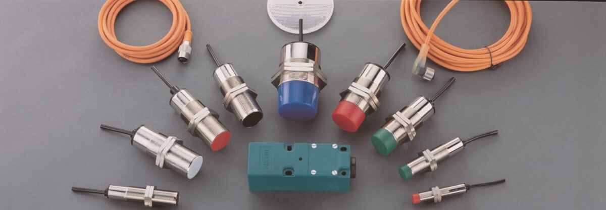
Capacitive Sensors for Plastic, Powder and Non-Metal Detection

An inductive switch cannot see plastic. Capacitive switches can, including through a container wall. How the D32C is specified, where it works, and the two mistakes that cause false triggering.

An inductive proximity switch sees metal and nothing else. That is not a limitation, it is the operating principle — it works by inducing eddy currents in a conductive target. Present it with a plastic bottle, a paper carton, a wooden pallet or a bin of powder and it will sit there indifferent.

Capacitive proximity switches solve that problem. They respond to a change in the dielectric in front of the sensing face, which means they detect essentially anything: plastic, liquid, powder, granulate, wood, glass, cardboard, and metal too.

How the sensing actually works

The sensing face forms one plate of a capacitor. The surroundings form the other. When a material enters the sensing field, the dielectric constant of the space in front of the face changes, the capacitance changes, and an internal oscillator circuit detects the shift and switches the output.

Two consequences follow, and they explain most of what is useful and most of what goes wrong.

Materials with a high dielectric constant are detected more easily. Water is detected extremely well. Metals behave as if they have an effectively infinite dielectric constant and are detected at the full rated distance. Dry plastics and powders have low dielectric constants and are detected at a reduced distance. This is why a sensor that detects a full bottle reliably may not detect an empty one.

The sensor cannot inherently distinguish target from contamination. A film of water, a dust build-up or a layer of product on the sensing face changes the dielectric just as a target does. This is the dominant failure mode in the field and it is a design problem rather than a device problem.

Sensing through a container wall

This is the application capacitive switches are genuinely unmatched at, and the one that brings most enquiries to us.

Mount the sensor on the outside of a non-metallic tank, hopper or pipe and set the sensitivity so that the wall alone does not trigger it but wall plus contents does. You then have a level switch with no penetration, no seal, no wetted part and nothing inside the vessel to clean. For food, pharmaceutical and chemical duty that is a substantial advantage.

What determines whether it will work:

  • Wall thickness and material. The wall consumes part of the sensing range. A thin polypropylene wall costs little; a thick glass-reinforced one may consume most of it.
  • The dielectric contrast between full and empty. Water against air is easy. Dry granulate against air is harder and needs care.
  • Whether product clings to the inside of the wall. If it does, the sensor reads full permanently. This is the single most common reason a through-wall installation fails, and it must be assessed before ordering rather than after.

Our note on capacitive proximity sensors for level detection goes into the level application in more depth.

Where capacitive switches earn their place

  • Packaging lines — detecting cartons, bottles, film and labels that inductive sensors cannot see.
  • Level in non-metallic vessels — high and low level switching without breaching the tank.
  • Powder and granulate handling — hoppers, silos, feed chutes and blocked-chute detection.
  • Plastics processing — presence of mouldings, sprue detection, bin-full signalling.
  • Timber and panel handling — board presence and edge detection.
  • Glass handling — where optical sensing is defeated by transparency.

The Accent capacitive range

Our capacitive proximity switches are M30 bodies with 10 mm sensing range, available across the full output matrix. The ordering code is straightforward once you know the pattern:

  • D32C-3010-NM-3S — NPN, normally open, 3-wire, 300 mA, short-circuit protected
  • D32C-3010-NB-3S — NPN, normally closed, short-circuit protected
  • D32C-3010-PM-3S — PNP, normally open, short-circuit protected
  • D32C-3010-PB-3S — PNP, normally closed, short-circuit protected

The same four are available without short-circuit protection as the -3 suffix rather than -3S. In almost every case the protected version is the right choice — the price difference is small and a shorted output on an unprotected sensor destroys it.

Reading the code: N or P selects NPN or PNP, M or B selects normally open (make) or normally closed (break), and 3S indicates 3-wire with short-circuit protection. If you are unsure whether your input card wants NPN or PNP, our guide to PNP and NPN sensors covers it.

Two mistakes worth avoiding

Setting the sensitivity at commissioning and never revisiting it. A capacitive sensor adjusted on a clean, dry morning will behave differently in humid weather and differently again with six months of product film on the face. Set it with margin, and specify a mounting position where the face can be wiped.

Mounting it where splash or condensation lands on the face. Water has a very high dielectric constant. A sensor that gets splashed will trigger on the splash. Shield it, angle it downward, or move it.

Specifying one

Tell us the target material, whether you are sensing it directly or through a wall, the wall material and thickness if so, the required sensing distance, whether the target is stationary or moving and how fast, the output your controller needs, and the environment — washdown, dust, temperature. If the target is a powder or granulate, the bulk density is worth including.

Need a price, a drawing or a stock check?

Send us the part number, or just describe the application and the target you need to sense. We will come back with the right model, a dimensional drawing and a quotation. Accent Controls has built sensors in Mumbai since 1985 and is the sole authorised distributor in India and SAARC for Novotechnik (Germany) and Contelec (Switzerland).

Request a quotation  ·  +91 98673 64004  ·  info@accentsensors.com
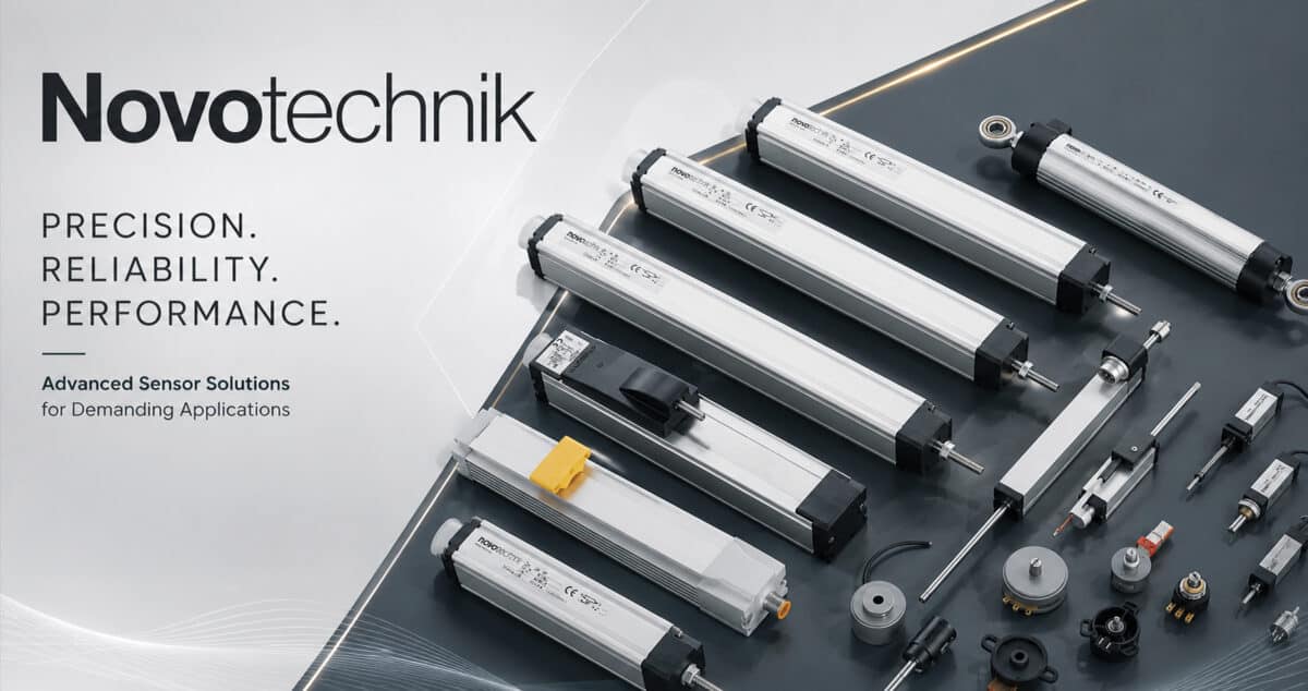
Hot Metal Detectors: What to Specify Before You Order

A hot metal detector is specified by geometry and timing, not by a catalogue number. The seven parameters that decide whether an HMD works on your mill, and the mistakes that cause false trips.

A hot metal detector looks like a simple device. It watches for the infrared signature of hot stock and gives a signal when it sees one. In practice HMD installations fail more often than almost anything else on a rolling mill, and they fail for reasons that are decided at specification, not at installation.

This guide sets out what actually needs to be established before ordering, based on the enquiries that come to us and the ones that come back six months later.

What the device is doing

Hot stock radiates. A hot metal detector is an infrared receiver aimed at a defined point in the pass line, with the sensitivity and optics arranged so that it responds to the radiation from the stock and ignores everything else in the mill.

Everything difficult about HMD selection follows from that second clause. A rolling mill is full of hot objects: adjacent stands, furnace doors left open, glowing scale on the floor, steam backlit by something hot, a neighbouring line. The specification problem is not detecting the bar. It is not detecting anything else.

1. Field of view and mounting distance

These two are a single decision, because field of view at the target is a function of the optical angle and the distance.

Mount too close and you lose tolerance — a bar that wanders laterally leaves the field and the detector drops out mid-pass. Mount too far and the field widens until it takes in the stand behind, and the detector never drops out at all because it can always see something hot.

Establish the actual mounting distance before selecting the device, and establish the lateral wander the pass line really has, not the nominal centre line. On a roughing mill that difference can be substantial.

2. The smallest target you must detect

Specify by the smallest and coolest stock the line runs, not the typical product. A detector configured around a 100 mm slab at full temperature will miss the tail end of a thin section that has cooled on a delay. The awkward end of the product range sets the requirement.

3. Response time against line speed

On a fast finishing mill the stock may be in the field of view for a very short time, and the detector output has to be present long enough for the PLC scan to catch it. Two separate things need checking: that the detector responds fast enough, and that the control system samples fast enough to see the response.

An HMD that works perfectly on the roughing side and misses intermittently on the finishing side is almost always this problem rather than a faulty device.

4. Temperature threshold

Too sensitive and the detector picks up residual heat, scale and radiated background. Too insensitive and it misses cooled tail ends. The threshold should be set from the coolest stock that must be detected, with margin, and then checked against the hottest background that must be ignored. If those two overlap, the geometry needs changing — no threshold setting will resolve it.

5. The environment the device has to survive

A rolling mill is a hostile place for electronics. Three things matter:

  • Ambient temperature at the mounting point. Not the mill ambient — the temperature where the device actually sits, which near a stand can be far higher.
  • Cooling and air purge. Most mill installations need cooling for the housing and a purge to keep the optical window clear. An air purge is not an optional extra; a dirty window is the most common cause of a detector that gradually stops working.
  • Water, scale and mechanical damage. Descaling spray, cobbles and maintenance traffic all reach places the designer assumed were protected.

Plan the purge air supply at the same time as the detector. Retrofitting it is expensive and frequently never happens.

6. Output and integration

Confirm what the control system expects — relay contact, transistor output, or an analogue signal — and the supply voltage available at the mounting point. On older mills the panel may have no DC supply where you need it, which changes the specification.

7. Alignment and maintenance access

The detector will need aligning during commissioning, and realigning after any mechanical work nearby. A device mounted where nobody can reach it safely with the line running will drift out of alignment and stay there. Specify the mounting bracket and access at the same time as the detector.

The three mistakes we see most often

Specifying from the catalogue instead of the geometry. The model number matters far less than field of view at the actual mounting distance.

No air purge. Works for three months, degrades slowly, gets blamed on the device.

Ignoring what else is hot. The single most common cause of false triggering, and the hardest to fix afterwards because it usually requires moving the mounting position.

Applications beyond rolling mills

Hot metal detectors are specified wherever hot stock has to be tracked without contact — continuous casting, forging lines, billet handling, furnace charging and discharge, shear control and cut-to-length. The specification logic is the same in each case: geometry first, timing second, environment third.

Getting a recommendation

Send us the mounting distance, the smallest and coolest stock to be detected, the line speed, what else is hot within the likely field of view, the ambient temperature at the mounting point, whether purge air is available, and the output your control system needs. A photograph or sketch of the intended mounting position is worth more than any of the individual numbers.

For background on how HMDs are used across a mill, see our overview of hot metal detectors in rolling mills.

Need a price, a drawing or a stock check?

Send us the part number, or just describe the application and the target you need to sense. We will come back with the right model, a dimensional drawing and a quotation. Accent Controls has built sensors in Mumbai since 1985 and is the sole authorised distributor in India and SAARC for Novotechnik (Germany) and Contelec (Switzerland).

Request a quotation  ·  +91 98673 64004  ·  info@accentsensors.com
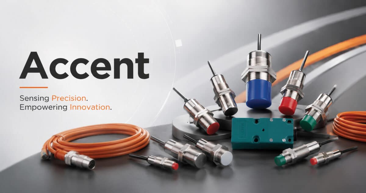
Proximity Sensor Dealers in India: Buying Direct or Through a Channel

Dealer, distributor, authorised distributor and reseller are not synonyms. What each route is genuinely good for, when going direct is worth it, and how to spot grey-market stock before it reaches site.

Dealer, distributor, authorised distributor, channel partner, reseller. In Indian industrial supply these words get used interchangeably, and they describe very different commercial relationships. The distinction is invisible when everything works and extremely visible when something fails.

Here is what each route actually is, what it is good at, and how to tell which one you are dealing with.

The four routes, honestly described

Direct from the manufacturer. You buy from whoever built the product. Best technical depth, best access to variants, best position on a warranty claim. Usually the right route for volume, for anything non-standard, and for products that will be supported over a plant lifetime.

Authorised distributor. A contracted relationship with the manufacturer, carrying factory warranty and factory technical escalation. This is the standard route for imported product — it is how a German or Swiss manufacturer serves India without operating here directly. Accent holds this relationship for Novotechnik and Contelec across India and SAARC.

Stockist or dealer. Buys from distributors, holds inventory, sells locally. Genuinely valuable when you need something today and the alternative is a week. The trade-off is that technical support is thin and the range is whatever moves fastest.

Reseller or trader. Buys wherever the price is lowest, including from other markets. Sometimes a legitimate surplus channel. Sometimes grey-market product with no supported warranty route. The difficulty is that it looks identical to the other three on a website.

When going direct is worth the effort

Direct is not automatically better. It is better in specific situations:

  • Volume orders. Pricing improves, and production can be scheduled against your delivery dates rather than drawn from someone inventory.
  • Anything non-standard. A specific cable length, a different connector, a housing variant. Dealers cannot authorise these; manufacturers can quote them.
  • Difficult applications. When the sensing problem is genuinely hard, you want the person who understands the electronics, not the person who understands the catalogue.
  • Long-life plant. A direct relationship with a manufacturer survives longer than a dealer relationship, and matters when you need the same part in year eight.
  • Certification requirements. Documentation comes from the manufacturer. Going through intermediaries adds delay and loses papers.

When a local stockist is the right answer

When the line is down and the part is standard. A stockist two hours away with the right M18 PNP switch on the shelf beats a better price arriving Thursday. Buy the emergency locally, then fix the underlying spares holding afterwards.

How to spot grey-market stock

This is the practical risk in the Indian market, and it is worth knowing the signals.

  1. The price is well below everyone else. Distribution margins are not large. A price substantially below the market usually means the product came in through an unofficial route, or it is old stock, or it is not what the label says.
  2. The seller will not put authorised in writing. Ask directly. An authorised party confirms it immediately.
  3. They cannot produce a full ordering code. Series names are public. Configuration codes come from the manufacturer ordering system.
  4. The warranty is theirs, not the manufacturer. A seller-backed warranty on imported product is the clearest signal there is.
  5. No documentation, or documentation later. Declarations of conformity and test certificates should accompany the goods.
  6. Vague delivery. Authorised channels can tell you whether something is in stock in India, in stock at the factory, or on a production run. Traders often cannot, because they are sourcing it after you order.

What we do

Accent occupies both positions, which is unusual and worth being explicit about.

For inductive, capacitive, photoelectric, magnetic and NAMUR proximity switches, we are the manufacturer — built in Mumbai since 1985 to IEC 60947-5-2, with variants quoted on request.

For Novotechnik linear and rotary position sensors, and for Contelec, we are the sole authorised distributor for India and SAARC, carrying factory warranty and factory engineering escalation.

The practical benefit is that one enquiry can cover both. A machine that needs twelve proximity switches and two linear transducers does not need two suppliers, two purchase orders and two warranty routes. If you want to verify the distribution claim rather than take it on trust, our guide on checking authorised Novotechnik stock explains exactly how.

Need a price, a drawing or a stock check?

Send us the part number, or just describe the application and the target you need to sense. We will come back with the right model, a dimensional drawing and a quotation. Accent Controls has built sensors in Mumbai since 1985 and is the sole authorised distributor in India and SAARC for Novotechnik (Germany) and Contelec (Switzerland).

Request a quotation  ·  +91 98673 64004  ·  info@accentsensors.com
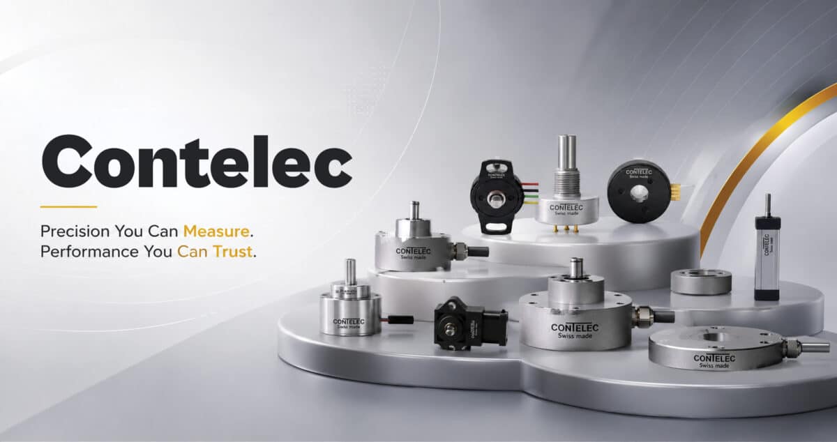
Proximity Sensor Manufacturers in India: A Buyer’s Checklist

Most proximity sensor suppliers in India are importers or rebadgers rather than manufacturers. Eight checks that separate a manufacturer from a box-shifter, and why it matters in year three.

Search for proximity sensor manufacturers in India and you will get a long list. Most of the companies on it do not manufacture anything. They import, they rebadge, or they assemble from bought-in modules — all legitimate businesses, but not the same thing, and the difference matters once you need a variant, a certificate, or a replacement for a part you bought four years ago.

This is the checklist we would use ourselves. It is deliberately written so that it can be applied to Accent as easily as to anyone else.

1. Ask what standard the product is built to

For inductive and capacitive proximity switches, the relevant standard is IEC 60947-5-2. It defines sensing distance and its tolerances, the standard target, switching frequency, and the behaviour that makes one manufacturer sensing distance comparable with another.

A supplier who cannot name the standard their product is built to is telling you something. A supplier who quotes a sensing distance without specifying whether it is rated, effective or assured operating distance is telling you something more subtle but just as useful — those three numbers differ, and the gap between them is where field failures live.

Accent manufactures to IEC 60947-5-2. Ask us for the figures against that standard and we will give them to you.

2. Ask to see where it is made

Not a photograph of a building. Ask whether you can visit, and watch how the question is received. A manufacturer will treat a plant visit from a serious buyer as normal. An importer will find reasons.

Our factory is in Vikhroli, Mumbai, and has been producing sensors since 1985.

3. Ask whether they can make a variant

This is the fastest way to establish what a supplier really is. Ask for a non-standard cable length, a different connector, or a specific housing material. A manufacturer will quote it, with a lead time and a quantity threshold. A reseller will explain why the catalogue option is better for you.

Variant capability is not a luxury. On an OEM machine build, being able to specify the exact cable length removes junction boxes, cable management and installation labour from every unit you ship.

4. Ask what happens to a part number in five years

Industrial plant outlives industrial catalogues. The question that matters on a twenty year asset is whether the same part will still be available, or whether you will be in a cross-reference exercise trying to establish what replaces it.

Importers are exposed here in a way manufacturers are not — when the overseas principal rationalises a range or changes distributor, the Indian supplier loses the part regardless of what they promised you.

5. Ask about traceability

Can they tell you which production batch a given serial number came from? If you are supplying into automotive, pharmaceutical or export machinery, your own quality system probably requires component traceability, and discovering at audit that your sensor supplier cannot provide it is an unpleasant surprise.

6. Separate the sensing distance claim from the application

A headline sensing distance is measured against a standard mild steel target under standard conditions. Your target is probably not that. Stainless steel, aluminium, brass and copper all reduce the effective sensing distance, some of them substantially — the correction is real and predictable, and a manufacturer will apply it for you without being asked.

If a supplier quotes the catalogue distance for an aluminium target without mentioning the reduction factor, they have not understood the application. Our note on reduction factors for different metals covers the arithmetic.

7. Check the range covers the awkward cases

Every supplier stocks M18 and M30 DC three-wire PNP. The range is tested by the things you need occasionally:

A supplier who has only the easy part of the range will leave you sourcing the rest from three other vendors.

8. Ask who answers a technical question

Not the sales contact — the engineer. On a difficult application, the value of a supplier is concentrated in the twenty minutes someone spends working out why a sensor is chattering. If there is no one to ask, the catalogue was the whole product.

Where imported product still wins

An honest checklist needs this section. Imported product is the right answer when you need something genuinely specialist that is not made domestically — high-precision absolute position measurement being the obvious case. That is why we distribute Novotechnik alongside our own manufacturing rather than pretending an inductive switch can do a linear transducer job.

The useful question is not Indian or imported. It is whether your supplier is willing to tell you which one your application actually needs.

Need a price, a drawing or a stock check?

Send us the part number, or just describe the application and the target you need to sense. We will come back with the right model, a dimensional drawing and a quotation. Accent Controls has built sensors in Mumbai since 1985 and is the sole authorised distributor in India and SAARC for Novotechnik (Germany) and Contelec (Switzerland).

Request a quotation  ·  +91 98673 64004  ·  info@accentsensors.com

NAMUR Proximity Switch Suppliers in India: Buying in Volume

Buying NAMUR switches in quantity is a different exercise from buying one. What actually drives the landed cost, why imported stock stalls projects, and what to ask a supplier before you commit a schedule to them.

Buying one NAMUR proximity switch is a catalogue exercise. Buying two hundred for a plant build, or committing to a call-off schedule for an OEM machine line, is a supply chain decision — and the things that matter change completely.

Accent Controls manufactures NAMUR inductive proximity switches in Mumbai. This page sets out what genuinely drives cost and delivery on volume orders, and the questions worth asking any supplier, including us.

Where the money actually goes

On a bulk NAMUR order, the unit price is rarely the largest variable. Three other factors usually move the landed cost more.

Customs duty and clearance on imported stock. A European NAMUR switch lands in India carrying duty, freight, clearance charges and an exchange rate you agreed weeks earlier. On a two hundred piece order those line items are not a rounding error. Domestically manufactured product removes them entirely, which is frequently a larger saving than any negotiation on unit price.

Minimum order quantities you did not want. Imported ranges are often stocked in Europe in pack sizes that suit European distribution. Needing 40 of an M18 8 mm and being quoted a box of 100 is a common and expensive outcome.

The cost of a stalled schedule. This is the one that hurts. If a plant build is waiting on a sensor delivery held at customs, the cost is not the sensor. It is the commissioning team standing idle and the liquidated damages clause in your contract.

Why the NAMUR range in particular causes delivery problems

NAMUR sensors are a specialist line. Distributors who stock general-purpose PNP and NPN inductive switches in depth frequently do not stock NAMUR variants at all, because turnover is lower. The sensor that was quoted from a catalogue in two days turns out to be on a six to eight week factory lead time.

The failure mode this produces is worse than a delay. Under schedule pressure, someone substitutes a standard three-wire sensor with a barrier and hopes it will pass. It will not — a conventional sensor cannot produce the diagnostic current band that makes NAMUR NAMUR, and the loop cannot be certified. The substitution gets discovered at inspection, and now you have a delay and a rework.

What manufacturing in India changes

Accent has built sensors in Mumbai since 1985, to IEC 60947-5-2. For a volume buyer that has a few practical consequences.

Lead time is a production question, not a shipping question. There is no ocean freight leg and no customs clearance in the critical path.

Quantities are what you asked for. Production runs are scheduled against the order rather than drawn from a European pack size.

Variants are possible. Cable length, connector type and housing details can be specified rather than accepted. On a large order this frequently removes an entire assembly operation at your end — a sensor supplied with the right cable length does not need a junction box.

A failure is a phone call. Warranty and technical support happen in the same time zone, in the same country, without a distributor relaying questions to a factory that answers overnight.

The standard range

Our NAMUR inductive proximity switches cover the thread sizes and sensing distances that account for the large majority of process plant requirements:

  • D20C-1204-NA — M12 body, 4 mm sensing
  • D20C-1805-NA — M18 body, 5 mm sensing
  • D20C-1808-NA — M18 body, 8 mm sensing
  • D20C-3010-NA — M30 body, 10 mm sensing
  • D20C-3015-NA — M30 body, 15 mm sensing

Pair them with our NAMUR control unit, which converts the sensor current signal into a relay output and indicates power, cable fault and relay status on the front panel. Ordering sensor and amplifier together is usually the right approach — see our guide to specifying intrinsically safe NAMUR loops.

Questions worth asking any NAMUR supplier

  1. Is this stock, or a factory lead time? Get the answer in weeks, in writing.
  2. What is the minimum order quantity per variant? Not per order — per variant. This is where quotations quietly inflate.
  3. Can cable length and connector be specified? If the answer is no, budget for the junction boxes.
  4. Who supplies the amplifier, and has this combination been used together?
  5. What certification documents come with the delivery, and when? Documents that arrive after the equipment are a common cause of inspection delays.
  6. What is the replacement route for a failure in year two? On a plant with a twenty year life, this outlasts most supplier relationships.

Getting a volume quotation

Send the quantity by variant, the required delivery schedule, whether you need a call-off arrangement, cable and connector requirements, and any certification the project specification demands. If you have a bill of materials, send it as it stands — we will mark up the equivalents rather than ask you to translate it first.

Need a price, a drawing or a stock check?

Send us the part number, or just describe the application and the target you need to sense. We will come back with the right model, a dimensional drawing and a quotation. Accent Controls has built sensors in Mumbai since 1985 and is the sole authorised distributor in India and SAARC for Novotechnik (Germany) and Contelec (Switzerland).

Request a quotation  ·  +91 98673 64004  ·  info@accentsensors.com
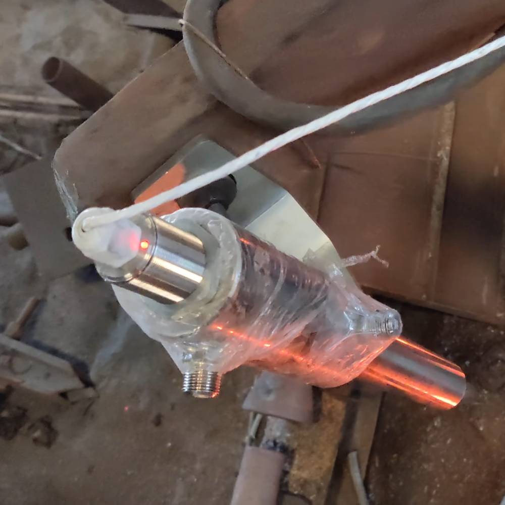
UL, CSA and Zone 0: Specifying Intrinsically Safe NAMUR Proximity Switches

Zone 0 does not permit an ordinary proximity switch, whatever its IP rating. What NAMUR actually standardises, how the barrier completes the safety case, and the approvals to confirm before you order.

Every few weeks we get an enquiry that reads roughly: we need an intrinsically safe NAMUR proximity switch, UL or CSA approved, suitable for Zone 0. It is a precise-sounding request that usually hides three separate decisions, and getting them confused is how projects end up with hardware that cannot be certified on site.

This guide separates them: what NAMUR actually is, what intrinsic safety requires beyond the sensor, and which approvals matter for which jurisdiction.

NAMUR is a signal standard, not a safety approval

This is the single most common misunderstanding. NAMUR — defined in IEC and EN 60947-5-6, and still occasionally called by its old designation DIN 19234 — specifies how a proximity switch communicates, not whether it is certified for a hazardous area.

A NAMUR sensor is a two-wire device with no output transistor. It does not switch a load. Instead it changes the current it draws from a nominal 8.2 V supply provided by an amplifier:

  • Target absent (undamped) — the sensor draws a higher current, typically above roughly 2.1 mA.
  • Target present (damped) — the sensor draws a lower current, typically below roughly 1.2 mA.

Because both normal states sit inside a defined, narrow band, anything outside that band is diagnostically meaningful. Near-zero current indicates a broken wire. Very high current indicates a short circuit. The amplifier can therefore distinguish a genuine fault from a legitimate sensor state — something a conventional three-wire PNP sensor simply cannot do, because its off state and a severed cable look identical.

That diagnostic capability is why NAMUR is used in process industries even outside hazardous areas. On a critical interlock, knowing that the sensor is healthy matters as much as knowing what it sees.

Why NAMUR and intrinsic safety go together

The second property of a NAMUR sensor is that it contains no energy storage of consequence and draws only milliamps. It is a simple apparatus in intrinsic safety terms. That makes it a natural building block for an intrinsically safe circuit, where the principle is to limit the electrical and thermal energy available in the hazardous area to below what can ignite the atmosphere present.

But the sensor alone does not create intrinsic safety. The loop does. An intrinsically safe installation is the sensor, the barrier or isolating amplifier, the cable, and the documented assessment that ties them together. Substituting any one element invalidates the case.

The barrier is not optional, and it is not an accessory

A NAMUR sensor cannot be wired directly to a PLC input. It needs an amplifier that supplies the 8.2 V, interprets the current, and presents a usable output to the control system. In a hazardous-area installation that amplifier also performs the energy limiting.

Our NAMUR control unit is built for exactly this arrangement: the sensor sits in the hazardous area and connects by two wires to the control unit, which is mounted in the safe area or inside a flameproof enclosure, and converts the low-current signal into a relay switching action. It works with inductive or capacitive NAMUR sensors, and carries three front-panel LEDs for power, cable fault and relay status — the cable fault indicator being the visible expression of the diagnostic band described above.

Specify the sensor and the amplifier together. Buying them separately from different sources is how loops end up unverifiable.

Zones, and why Zone 0 is a different conversation

Hazardous areas are classified by how often an explosive atmosphere is actually present:

  • Zone 0 — present continuously, or for long periods. Inside tanks and vessels, typically.
  • Zone 1 — likely to occur in normal operation.
  • Zone 2 — unlikely in normal operation, and short-lived if it occurs.

Zone 0 is the demanding case, and it is where specifications need to be exact rather than approximately right. Equipment for Zone 0 requires the highest protection level, and the assessment covers the whole loop rather than the sensor in isolation. If your application is genuinely Zone 0 — inside a solvent tank, for example, rather than in the bunded area around it — say so at the enquiry stage. The difference changes the hardware.

It is worth confirming the zone classification with whoever produced your area classification drawing before ordering. A surprising number of enquiries specify Zone 0 for locations that are correctly classified Zone 1, which widens the available options considerably.

UL, CSA, ATEX, IECEx: which one you need

Approval schemes are regional, and the right one depends on where the plant is and who is signing it off.

  • ATEX — the European scheme, and the one most often referenced in Indian project specifications because so much process plant is built to European standards.
  • IECEx — the international scheme, widely accepted and often the most practical route for equipment crossing borders.
  • UL and CSA — the North American schemes. These appear in Indian enquiries mainly where the end client, the licensor or the EPC contractor is American or Canadian, or where the plant is being built for export.

These are not interchangeable, and a certificate under one scheme does not automatically satisfy an inspector working to another. Establish which scheme your project actually requires before the technical bid evaluation, not after.

What to confirm before you order

  1. The zone, gas group and temperature class from your area classification document — not an estimate.
  2. Which approval scheme the project specification calls for, and who accepts it.
  3. Whether the certification must cover the loop or only the sensor. This determines whether the barrier must be bought as a matched pair.
  4. Sensing distance and target material, remembering that an inductive sensor sees non-ferrous metals at a reduced distance.
  5. The thread size and sensing range your mounting allows.
  6. Cable length and routing, because intrinsic safety calculations are affected by cable capacitance and inductance over long runs.

The Accent NAMUR range

We manufacture NAMUR inductive proximity switches in Mumbai in M12, M18 and M30 threads, with sensing distances from 4 mm to 15 mm:

  • D20C-1204-NA — M12, 4 mm
  • D20C-1805-NA — M18, 5 mm
  • D20C-1808-NA — M18, 8 mm
  • D20C-3010-NA — M30, 10 mm
  • D20C-3015-NA — M30, 15 mm

Because approval requirements vary so much by project and by jurisdiction, tell us which scheme and which zone your specification calls for when you enquire, and we will confirm exactly what we can supply against it and what the documentation package looks like. That is a better conversation to have before the purchase order than during commissioning.

For background on how NAMUR sensors behave electrically, see our explainer on NAMUR proximity sensors.

Need a price, a drawing or a stock check?

Send us the part number, or just describe the application and the target you need to sense. We will come back with the right model, a dimensional drawing and a quotation. Accent Controls has built sensors in Mumbai since 1985 and is the sole authorised distributor in India and SAARC for Novotechnik (Germany) and Contelec (Switzerland).

Request a quotation  ·  +91 98673 64004  ·  info@accentsensors.com

Novotechnik RFC-4800 Touchless Rotary Sensor: India Buying Guide

The RFC-4800 is Novotechnik touchless absolute rotary sensor with analogue, digital and fieldbus interfaces. How to specify it, and when to choose it over the RSC-2800.

The RFC-4800 is Novotechnik robust touchless absolute rotary sensor, and it is the unit we are asked for most often when an application has already destroyed something else. That is not an accident — the reason buyers arrive at this series is almost always that a contacting sensor has worn out, or that the shaft cannot be mechanically coupled at all.

This guide sets out what the series does, the interface decision that drives the ordering code, and how to choose between the RFC-4800 and the RSC-2800.

What touchless actually buys you

In a traditional potentiometric rotary sensor, a wiper rides on a resistive track. That design is accurate, cheap and very well understood, and it has one inherent limitation: the wiper and the track are in physical contact, so they wear. In a high-cycle application the track eventually develops a worn band, and the output becomes noisy exactly in the region the machine uses most.

The RFC-4800 uses NOVOHALL magnetic sensing instead. A magnet moves with the shaft, the sensing element reads the field, and nothing touches anything. Three consequences follow:

  • Cycle life stops being the limiting factor. There is no measuring-path wear mechanism to consume.
  • The sensor can be sealed more thoroughly, because there is no requirement for a mechanical path into the measuring element.
  • Mechanical decoupling becomes possible. In some configurations the magnet and the electronics can be separated, which matters where the shaft cannot accept a coupling or where vibration would destroy a coupled unit.

It is absolute, so position is known at power-up without a reference run — important on equipment that must resume safely after a power failure rather than homing first.

The interface decision

The RFC-4800 carries an unusually broad interface range: analogue, digital and fieldbus. That breadth is the main reason it gets specified into machine builds rather than just repairs.

Analogue — voltage or current, for conventional PLC analogue inputs. Current output remains the safer choice on long cable runs and in electrically noisy plants.

Digital — absolute serial output, avoiding the resolution loss and drift of an analogue chain. Worth specifying where accuracy is the point of the exercise.

Fieldbus — the option that distinguishes this series in practice. If your machine is already built around a bus, taking position onto the bus removes an analogue input card, the associated wiring, and a calibration step. We see steady Indian enquiry volume for CANopen position sensors specifically, mostly from machine builders standardising on a single bus across a platform.

Confirm the exact protocol and profile your controller expects before ordering. Fieldbus variants are configured to the protocol, and this is not something that can be changed after delivery.

RFC-4800 or RSC-2800?

Both are touchless NOVOHALL single-turn rotary sensors from the same manufacturer, so the choice is rarely about accuracy. It is about how the sensor mounts and what it has to talk to.

  • Choose the RSC-2800 when you want a compact shaft-type unit with a straightforward analogue, SSI, incremental or SPI interface, and the mechanical arrangement allows a normal coupling. It also offers ratiometric output and E1 type approval, which matters for mobile machinery.
  • Choose the RFC-4800 when the application is mechanically hostile, when you need fieldbus, or when the installation would benefit from separating the magnet from the electronics.

If you are unsure, send us the mechanical arrangement and the controller type and we will tell you which is the better fit. The wrong answer here is usually discovered at commissioning, which is the expensive moment to discover it.

Specifying it correctly

The information that pins down an RFC-4800 ordering code:

  • Measuring angle required, and whether it must cover a full 360 degrees
  • Interface, and for fieldbus the exact protocol the controller speaks
  • Supply voltage available at the sensor
  • Protection rating demanded by the environment, including washdown regime
  • Worst-case temperature at the mounting point, not the plant ambient
  • Mechanical arrangement — shaft diameter, available depth, and whether a coupling is possible at all
  • Whether redundant outputs are required for a safety function

Buying it in India

Accent Controls is the sole authorised Novotechnik distributor for India and SAARC. Ordering through the authorised channel means factory warranty, traceable supply and an engineering route back to the manufacturer if the application turns out to be unusual. Our guide to verifying authorised Novotechnik stock covers the checks worth running on any supplier, including us.

Need a price, a drawing or a stock check?

Send us the part number, or just describe the application and the target you need to sense. We will come back with the right model, a dimensional drawing and a quotation. Accent Controls has built sensors in Mumbai since 1985 and is the sole authorised distributor in India and SAARC for Novotechnik (Germany) and Contelec (Switzerland).

Request a quotation  ·  +91 98673 64004  ·  info@accentsensors.com
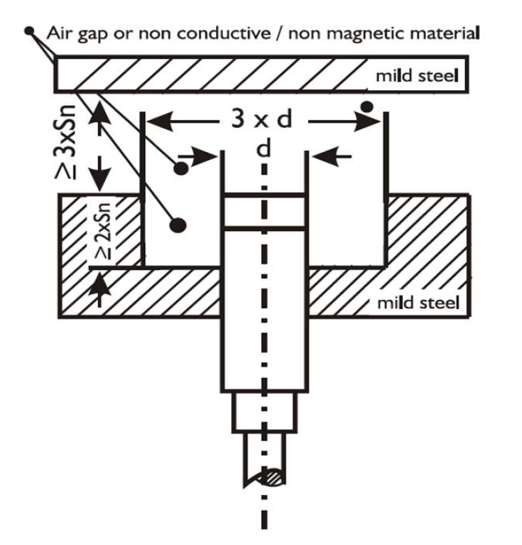
Novotechnik RSC-2800 in India: Interfaces, Variants and How to Order

The RSC-2800 is a touchless NOVOHALL single-turn rotary sensor with six interface options and three protection bands. Here is how to pin down the variant you actually need before you order.

The RSC-2800 is one of the most frequently specified Novotechnik rotary sensors in India, and one of the most frequently mis-ordered. The reason is simple: RSC-2800 is not a product, it is a family. Six interface options, three protection bands, an unusually wide temperature range and optional redundancy mean that two units carrying the same series name can behave quite differently on the machine.

This guide walks through the decisions that set the ordering code, so that what arrives is what your control system expects.

What the RSC-2800 is

It is an absolute, non-contacting rotary sensor built on Novotechnik NOVOHALL magnetic technology. Absolute means it reports true shaft angle immediately at power-up, with no homing move and no reference run. Non-contacting means there is no wiper riding on a resistive track, which removes the dominant wear mechanism in traditional potentiometric rotary sensors.

That combination is why it turns up on mobile machinery, on automotive test rigs, and on plant equipment where a sensor failure means a shutdown rather than an inconvenience. There is no mechanical contact in the measuring path to wear out.

Decision one: the interface

This is the choice that most often goes wrong, because the series supports six and the label does not always make the difference obvious.

  • Voltage output — the default assumption for most PLC analogue input cards. Simple, well understood, and sensitive to cable length and ground offset over long runs.
  • Current output — the right answer whenever the cable run is long or the environment is electrically noisy. A current loop does not care about voltage drop down the cable, which in an Indian plant with a 40 metre run back to the panel is usually the deciding factor.
  • Ratiometric — output scales with supply voltage rather than holding an absolute value. Correct when the receiving controller shares and measures the same supply, wrong when it does not. Worth checking carefully, because a ratiometric unit fed into a fixed-scale input reads plausibly but drifts with supply.
  • SSI — synchronous serial, for absolute digital position without analogue conversion losses. Choose this when resolution matters and the controller supports it.
  • Incremental — pulse output, for retrofits into counters and drives already built around incremental feedback.
  • SPI — for direct integration into embedded electronics rather than a plant PLC.

If you are replacing an existing sensor, match the interface to what the controller is wired for, not to what seems technically better. An upgrade from voltage to SSI is a control system change, not a sensor swap.

Decision two: protection rating

The RSC-2800 is available from IP54 up through IP65 and IP67. The practical guidance:

  • IP54 is adequate inside a reasonably clean enclosure, where the sensor sees dust but never direct water.
  • IP65 handles hose-down and general plant wash.
  • IP67 covers temporary immersion — the right choice for mobile machinery, outdoor installation, and anywhere monsoon exposure is realistic.

Specify by the worst case the unit will actually see, not the normal condition. The failure mode for an under-rated sensor is water ingress at the cable entry, and it typically appears months after commissioning.

Decision three: temperature range

The series covers from below minus 40 degrees Celsius up to above plus 85. Very few Indian applications need the cold end, but the hot end matters more than people allow for. A sensor mounted near a furnace, on a hydraulic power pack, or inside an unventilated panel in a Gujarat summer can sit far above the ambient air temperature. Measure at the mounting point in the worst month rather than taking the plant ambient figure.

Decision four: redundant outputs and E1 approval

Two options exist on this series that are worth knowing about before you need them.

Redundant outputs provide two independent measuring channels in one housing, so a controller can cross-check them and detect a fault rather than acting on a wrong reading. If the angle measurement feeds anything safety-related, raise this at the enquiry stage — retrofitting redundancy means changing the sensor.

European E1 type approval is available on this series. If you are building vehicles or mobile machinery for export, confirm whether your compliance route requires it before you order.

Mechanical fit

The RSC-2800 is a shaft-type design. The mating question is the coupling: a rigid coupling transfers any shaft misalignment straight into the sensor bearing and shortens its life, so a flexible or backlash-free coupling is normally the right choice. If you are replacing a blind hollow shaft unit, note that RSC-3200 is the hollow-shaft member of the same family. Novotechnik no longer recommends it for new designs, so treat it as a like-for-like replacement part rather than a specification for a new machine, and ask us for the current equivalent.

Ordering

Send us whichever of these you have and we will return the full ordering code with a price and a drawing:

  • Measured angle range in degrees
  • Output type, and the controller or input card it feeds
  • Supply voltage available at the sensor
  • Protection rating required, and whether washdown occurs
  • Worst-case temperature at the mounting point
  • Whether redundant outputs are needed
  • The existing part number and a photograph of the label, if this is a replacement

Accent Controls is the sole authorised Novotechnik distributor for India and SAARC, so the quotation covers factory warranty and traceable supply. See also our guide to checking you are buying authorised Novotechnik stock, and the wider single-turn rotary sensor range.

Need a price, a drawing or a stock check?

Send us the part number, or just describe the application and the target you need to sense. We will come back with the right model, a dimensional drawing and a quotation. Accent Controls has built sensors in Mumbai since 1985 and is the sole authorised distributor in India and SAARC for Novotechnik (Germany) and Contelec (Switzerland).

Request a quotation  ·  +91 98673 64004  ·  info@accentsensors.com
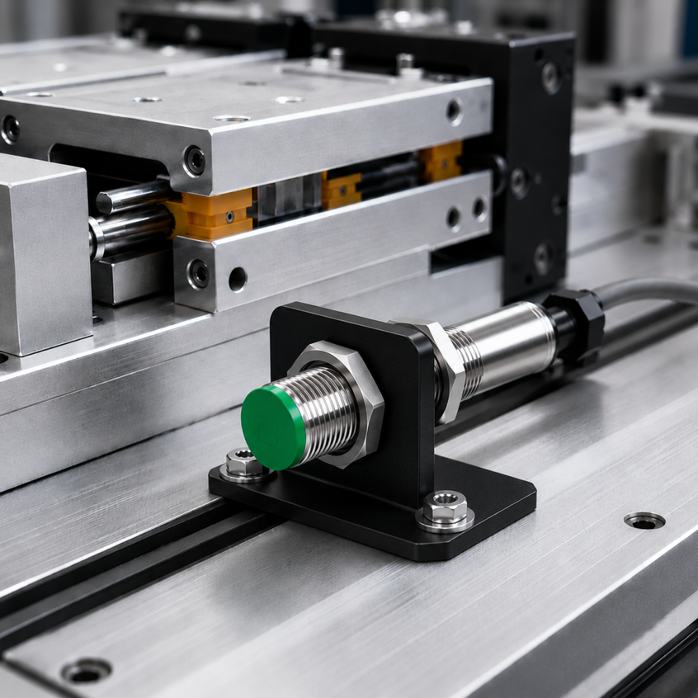
Novotechnik Distributor in India: How to Check You Are Buying Authorised Stock

Accent Controls is the sole authorised Novotechnik distributor for India and SAARC. What authorised supply actually changes, six checks before you release a purchase order, and what grey-market stock really costs.

Buying a Novotechnik position sensor in India is easy. Buying one that still carries a factory warranty, a traceable production record, and access to the manufacturer when something goes wrong is a different exercise — and the gap usually only becomes visible much later, on a line that has already stopped.

Accent Controls (P) Ltd is the sole authorised distributor for Novotechnik (Germany) across India and the SAARC region. This guide covers what that changes for you as a buyer, the checks worth running before you release a purchase order, and what unofficial stock actually costs once you account for the failure you cannot get supported.

What authorised distribution actually changes

Authorised is a contractual relationship with the manufacturer, not a description a seller can award themselves. Four things follow from it.

Factory warranty, honoured by the factory. A unit bought through the authorised channel is registered against the manufacturer warranty terms. A unit bought outside it is covered by whatever the seller chooses to offer, for as long as that seller stays in business. When a sensor fails inside a press or a mill, the question is not whether someone will argue about it. It is who physically replaces the part, and how fast.

Traceability to a production batch. Novotechnik sensors carry batch and serial identification, and through the authorised channel that number resolves to a real production record. This matters more than buyers expect. If you are supplying machinery that carries a CE mark, or working to a customer quality plan that requires component traceability, an untraceable sensor is an audit finding waiting to happen.

The right variant, not the closest one in stock. Most Novotechnik series are families, not single products. RSC-2800 alone spans voltage, current, SSI, incremental, ratiometric and SPI interfaces, three protection rating bands, and optional redundant outputs. A reseller clearing inventory offers you what they hold. An authorised distributor configures the part number against your application.

Engineering escalation. Application questions — permissible shaft loading, cable routing in an electrically noisy plant, whether a redundant output is genuinely required for your safety case — route back to the manufacturer through the distributor. Outside the channel there is nobody to ask.

Six checks before you release the purchase order

  1. Ask the seller to state in writing that they are an authorised Novotechnik distributor for India. Authorised parties do this without hesitation. It also creates a record if the claim later proves false.
  2. Ask who honours the warranty. If the answer is the seller rather than the manufacturer, you are buying grey-market stock regardless of what the website says.
  3. Ask for the full ordering code, not the series name. RFC-4800 is a family. The part you need is a specific configuration. A seller who cannot produce the complete code is unlikely to be able to source the right variant.
  4. Ask for the date code. Seals age. Long-warehoused stock is a common feature of unofficial supply, and it is invisible until the first washdown.
  5. Ask for the declaration of conformity, and the E1 type approval where it applies. Several Novotechnik rotary series carry European E1 automotive type approval. If your application depends on it, get the paperwork before the order, not after.
  6. Ask what happens if it fails in month fourteen. The answer tells you which channel you are actually in.

What unofficial stock actually costs

The headline saving on grey-market Novotechnik is usually modest — a few percent, occasionally ten. Set that against the realistic downside.

A position sensor is rarely expensive relative to the machine it sits in, but it is frequently on the critical path: a rotary sensor on a mill screwdown, a linear transducer on an injection moulding machine, a multi-turn unit on a crane hoist. When it fails and there is no supported replacement route, the cost is not the sensor. It is the line.

The second cost is slower and harder to see. Unsupported stock tends to be the almost-right variant — close enough to fit, not close enough to behave. An analogue output where the controller expected ratiometric. A protection rating one step below what the washdown regime demands. A temperature range that is comfortable during commissioning and marginal in May. Faults like these do not present cleanly. They drift, and they get blamed on the PLC for a year.

The Novotechnik range held for India

Accent supplies the full Novotechnik programme. In practice, Indian demand concentrates in three areas.

Single-turn rotary sensors — the RSC, RFC, RSA, RSB, RSM, RSX and RFD families, covering angle measurement up to 360 degrees in both contacting and touchless NOVOHALL magnetic designs. RFC-4800 is the most widely specified touchless unit here, largely because the interface options run from simple analogue through to fieldbus.

Linear position transducers — TR and TRS, TX2, TEX, TE1, LWH, LWG, LWX, TLH, TH1, TM1 and TP1, plus spring-return variants. Stroke length, mounting style (rod, side-actuated, pivot head, mounting clamp) and whether a return spring is needed are the three decisions that set the part number.

Multi-turn rotary sensors — MB1-3600, MC1-2800, MZ1-2200 and RMB-3600, for shafts that turn through more than one revolution where absolute position has to survive a power cycle.

What to send us when you enquire

The fastest route to a correct quotation is a short set of facts:

  • The existing part number if you are replacing a unit, including the full ordering code from the label if it is still legible
  • Measurement range — degrees of rotation, or stroke in millimetres
  • Output required, and what it connects to
  • Supply voltage available at the sensor
  • Protection rating the environment demands, and whether there is washdown
  • Ambient temperature range, worst case rather than nameplate
  • Mechanical interface: shaft, hollow shaft, rod, side actuation, and any coupling already in place

If you have a drawing, or simply a photograph of the installed unit and its label, send that instead. It usually answers more questions than a specification sheet does.

Need a price, a drawing or a stock check?

Send us the part number, or just describe the application and the target you need to sense. We will come back with the right model, a dimensional drawing and a quotation. Accent Controls has built sensors in Mumbai since 1985 and is the sole authorised distributor in India and SAARC for Novotechnik (Germany) and Contelec (Switzerland).

Request a quotation  ·  +91 98673 64004  ·  info@accentsensors.com
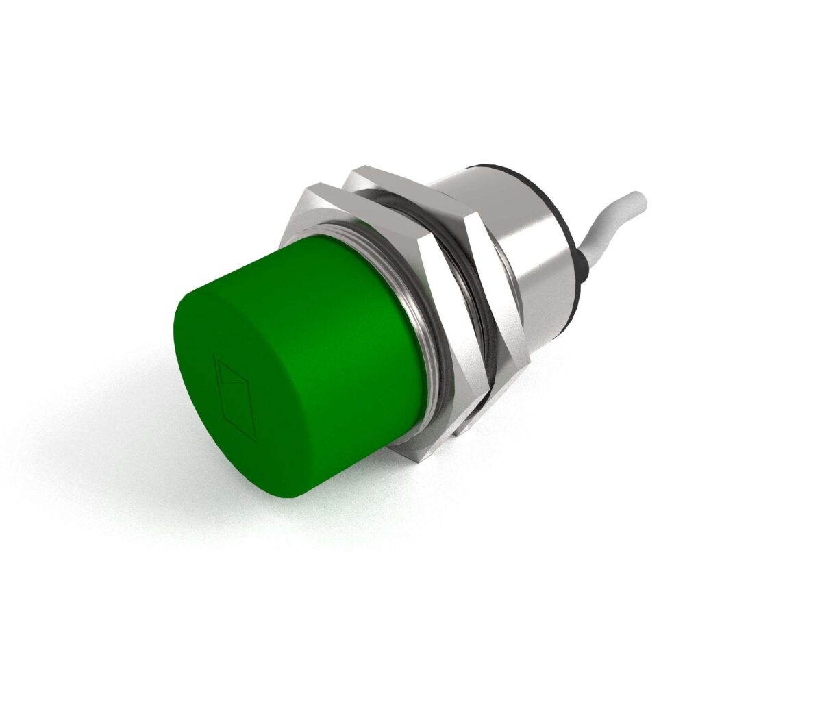
Linear Position Transducers: Potentiometric vs LVDT vs Magnetostrictive

Three ways to measure linear position, compared on stroke, wear, environment and cost — plus the rotary equivalents and a six-point specification checklist.

Choose a potentiometric transducer when you want absolute position, a simple ratiometric output and low cost. Choose LVDT when you need a sealed, contactless element over a short stroke in a harsh or high-vibration environment. Choose magnetostrictive when the stroke is long, the duty is continuous, and wear is unacceptable — typically inside hydraulic cylinders.

Quick reference

  • Potentiometric — contact wiper on a conductive plastic track. Absolute, ratiometric, inexpensive, strokes from a few mm to over a metre.
  • LVDT — moving core in a transformer. Contactless element, excellent resolution, short to medium stroke, tolerant of shock.
  • Magnetostrictive — timed torsional pulse along a waveguide. Contactless, absolute, strokes to several metres, ideal in hydraulics.
  • All three give absolute position — no homing needed on power-up, unlike an incremental encoder.
  • Selection usually turns on stroke length, duty cycle and environment, not on accuracy.

How each technology works

Potentiometric

A wiper travels along a resistive track — in a quality industrial transducer, conductive plastic rather than wirewound. The output is a voltage divider: apply an excitation voltage across the track and read the wiper. Because the output is a fixed ratio of the excitation, drift in the supply cancels out, which is why potentiometric sensors are described as ratiometric and why they tolerate modest power supplies so well.

The wiper is a physical contact, so there is a wear mechanism. Modern conductive-plastic elements are rated for very large numbers of movements, and in most industrial duties the transducer outlives the machine. High-frequency dithering in one small part of the track is the case where wear genuinely bites.

LVDT

A linear variable differential transformer has one primary and two secondary windings, with a ferromagnetic core free to move inside. The primary is excited with AC; the two secondaries are wired in opposition. With the core centred their outputs cancel. As it moves, one secondary dominates, and the amplitude and phase of the difference give position.

The core does not touch the windings, so there is nothing to wear. The winding assembly can be fully sealed and even hermetically welded, and the whole device is essentially insensitive to shock and vibration. Resolution is limited only by the electronics, which is why LVDTs remain standard in test rigs and aerospace.

Magnetostrictive

A current pulse is launched down a magnetostrictive waveguide. A permanent magnet, carried on the moving element, sits somewhere along that waveguide. Where the pulse’s field meets the magnet’s field, a torsional strain wave is generated and travels back to a pickup at the head. Measure the time of flight, multiply by the known wave velocity, and you have absolute position.

Nothing touches. The magnet can be separated from the waveguide by a non-magnetic barrier, which is why these sensors can be installed inside a hydraulic cylinder through a gun-drilled rod, with the rod itself acting as the pressure boundary.

Direct comparison

  Potentiometric LVDT Magnetostrictive
Contact Wiper on track None None
Typical stroke 10 mm – 1 m+ 1 mm – 500 mm 50 mm – several metres
Absolute output Yes Yes Yes
Output type Ratiometric voltage; conditioned 0–10 V / 4–20 mA versions available AC differential, or DC with built-in conditioning Analogue, SSI, CANopen, IO-Link and others
Wear mechanism Wiper and track Bearings only, if fitted None in the sensing path
Vibration tolerance Good Excellent Very good
Suits hydraulic cylinder installation Rarely Occasionally Yes — the standard solution
Relative cost Low Medium to high High
Electronics required Minimal Oscillator and demodulator Integrated, always

Choosing by application

Application Usual choice Reason
Injection moulding — screw and clamp position Potentiometric or magnetostrictive Long stroke, continuous cycling; magnetostrictive where duty is extreme
Hydraulic cylinder feedback Magnetostrictive Mounts inside the cylinder; no seal to fail on a moving rod
Valve and actuator position Potentiometric Short stroke, low duty, cost matters
Materials test rig LVDT Resolution and shock tolerance outweigh cost
Aerospace control surface LVDT Sealed, contactless, proven in the sector
Packaging machine format adjustment Potentiometric Infrequent movement, absolute readout on power-up
Steel mill roll gap Magnetostrictive or LVDT Environment and duty rule out contact devices
Machine tool axis Neither — use a linear encoder Micron-level accuracy over long travel

Rotary equivalents

The same logic applies to angular measurement. A rotary single-turn sensor covers up to 360° and suits throttle, damper and valve positions. Where the shaft turns through many revolutions — a screw jack, a cable drum, a steering column — a rotary multi-turn sensor keeps an absolute count across the whole travel, so position is known immediately on power-up with no homing move.

Contactless rotary sensors using Hall-effect or inductive principles have largely displaced potentiometric rotary units in high-cycle duties, for exactly the wear reasons described above.

Specification checklist

  1. Stroke and mounting length. The installed length always exceeds the electrical stroke. Confirm the mechanical envelope before selecting.
  2. Linearity you actually need. Independent linearity is usually quoted as a percentage of full stroke; over a long stroke a good percentage is still a large absolute error. Ask for the number in millimetres.
  3. Duty cycle. Movements per day, and whether the motion concentrates in one part of the stroke. This decides whether a contact device is acceptable.
  4. Output interface. Match the controller: ratiometric voltage, 0–10 V, 4–20 mA, SSI, CANopen or IO-Link. Retrofits usually dictate this.
  5. Environment. Temperature, vibration, ingress and any chemical exposure — see our guide to IP ratings and what each test proves.
  6. Coupling. A rigid coupling between machine and transducer transmits misalignment straight into the element and shortens its life. Use the specified ball joint or flexible coupling.

Accent Controls is the sole authorised distributor in India and SAARC for Novotechnik of Germany and Contelec of Switzerland, alongside the proximity and photoelectric sensors we manufacture in Mumbai. That means we can specify contact and contactless position measurement from the same conversation — see our overview of position sensor solutions.

Frequently asked questions

What is the difference between a linear transducer and a linear encoder?

A transducer of the types described here gives an absolute analogue or digital position over its stroke, typically at millimetre to sub-millimetre resolution, and needs no homing on power-up. A linear encoder — usually optical or magnetic scale — targets much finer resolution over machine-tool travels and is often incremental, requiring a reference move after power-up. They solve different problems at different price points.

Do potentiometric transducers wear out?

The wiper and track are a contact pair, so yes in principle. In practice a good conductive-plastic element is rated for a very large number of movements and outlasts the machine in most industrial duties. The exception is high-frequency dithering concentrated in one small region of the stroke, which wears a localised flat and shows up as noise at that position — a contactless technology is the right answer there.

Can a magnetostrictive sensor be fitted inside a hydraulic cylinder?

Yes, and it is the standard solution for cylinder position feedback. The waveguide is installed in a gun-drilled bore in the piston rod, with the position magnet on the piston. Nothing penetrates the pressure boundary and there is no dynamic seal on a moving sensor element, which is exactly why the arrangement is so reliable.

Which is most accurate?

LVDTs generally offer the best resolution and repeatability over short strokes, because resolution is limited by the electronics rather than by any physical division. Over long strokes magnetostrictive devices are usually the most accurate in absolute terms. But for most industrial applications repeatability and long-term stability matter more than headline accuracy — specify what the machine needs rather than the best number available.

Do I need a linear transducer or would proximity switches do?

If you only need to know that the axis has reached a small number of fixed positions, proximity switches are simpler, cheaper and more robust — see our inductive proximity switch range. A transducer is warranted when you need continuous position, when the target positions change with the product format, or when the controller closes a loop on position.

Selecting position measurement for a machine? Tell us the stroke, the duty cycle, the controller interface and the environment. As the authorised Novotechnik and Contelec distributor for India and SAARC, Accent Controls can quote potentiometric, LVDT-class and contactless options side by side.

Discuss a position sensor Linear position transducers About Accent Controls

Proximity Sensor Troubleshooting: 12 Common Faults and How to Diagnose Them

Most sensor failures are not failed sensors. Twelve faults in diagnostic order, a symptom index, and the five-step bench test that tells you where the problem really is.

Most proximity sensor “failures” are not failed sensors. In the field the usual causes are, in order: the gap has drifted beyond the assured sensing distance, the target material is not what the sensor was sized for, the wiring polarity does not suit the PLC input, or electrical noise from a nearby drive is corrupting the signal. Work through them in that order before replacing anything.

Diagnose in this order

  • 1. Power — measure at the sensor, not at the terminal rail.
  • 2. Output — does the sensor switch at all? Watch the LED, then meter the output.
  • 3. Gap and target — is the working gap inside 0.81 × Sn × reduction factor?
  • 4. Interface — polarity, leakage current, input card common.
  • 5. Environment — noise, temperature, vibration, contamination.

The twelve faults, and how to identify each

1. Sensor never operates — no LED, no output

Measure supply voltage at the sensor connector, with the machine running. A long cable run, a corroded terminal or an overloaded 24 V supply can drop several volts under load. Below the sensor’s minimum operating voltage the oscillator will not start. If the supply is good, check polarity: brown to +, blue to 0 V. Most sensors survive reversal, but they do not operate.

2. LED lights but the PLC never sees it

The sensor is working; the interface is not. Check whether you have a PNP sensor on a sourcing input card, or an NPN sensor on a sinking one — the two must be opposites. This is the single most common commissioning fault, and our guide to PNP versus NPN wiring explains how to confirm which you have.

3. PLC input reads permanently ON

With a two-wire sensor, this is almost always residual leakage current holding a high-impedance input above its OFF threshold. Fit a bleeder resistor across the input or move to a three-wire sensor. With a three-wire sensor, suspect a short between the output core and the supply, or an unshielded non-flush sensor detecting its own mounting bracket.

4. Intermittent — works cold, fails hot

This is the classic symptom of designing to the catalogue sensing distance instead of the assured distance. Rated distance Sn is a nominal figure; guaranteed detection only exists inside 0.81 × Sn, and that must be further multiplied by the reduction factor for the target material. Measure the actual gap and recalculate. Nine times in ten the gap is too large.

5. Detection distance is far shorter than the catalogue says

Check the target material first. Aluminium at a reduction factor of about 0.4 gives you well under half the rated range; copper less still. Then check target size — a target smaller than the reference square loses range roughly in proportion to area. Then check thickness and any plating.

6. Unshielded sensor latches on permanently

It is detecting its own mounting. A non-flush sensor needs a metal-free zone: a clear diameter of at least three times the barrel diameter, with the head standing proud of surrounding metal by at least twice Sn. Either move it out or fit a shielded sensor — see shielded versus unshielded mounting.

7. Two adjacent sensors chatter randomly

Mutual interference. Two inductive sensors mounted too close beat against each other and both outputs become unstable, typically worsening as they warm. Minimum spacing is twice the barrel diameter for shielded units and three times for unshielded. If the layout cannot be changed, specify units with different oscillator frequencies.

8. Random false triggers when a drive or contactor operates

Electrical noise. Confirm by operating the drive with the machine mechanically stationary — if the sensor still trips, it is not seeing a target. Route sensor cables away from VFD motor cables, never in the same trunking or parallel for long runs. Use screened cable with the screen earthed at the panel end only. Add a suppressor across any inductive load switched near the sensor.

9. Output is on but the load will not operate

Check load current against the sensor’s rated output current — typically 100–200 mA for a DC three-wire unit. Contactor coils and lamps often exceed it. Also check voltage drop, particularly with two-wire sensors in series, where the drops add and can starve the load. Our note on two, three and four-wire wiring covers the arithmetic.

10. Works, then dies after a few weeks

Look for mechanical and environmental causes. Vibration loosens locknuts and fatigues cable at the strain relief — flex the cable at the entry and see if the LED flickers. Coolant or washdown ingress past a degraded seal is next. Check the sensor’s IP rating against the actual environment, remembering that the connector is part of the seal.

11. Missing targets at speed

Every sensor has a maximum switching frequency, and the target must remain in the field long enough to be recognised. Calculate the dwell time: target length divided by line speed. If it approaches the sensor’s response time, you need a faster sensor, a longer target flag, or a different sensing position. See our note on proximity switches in high-speed counting.

12. Capacitive sensor stays on after the product has gone

Build-up on the sensing face or product clinging to the inside of a tank wall. The sensor is behaving correctly — high-dielectric material is still in its field. Reduce sensitivity so bulk product is needed rather than a film, and relocate to a point with flow across it. Details in our guide to capacitive sensors for level detection.

A bench test that settles most arguments

When a sensor is suspected, remove it from the machine and test it on a bench with nothing else connected:

  1. Apply rated supply — brown to +24 V, blue to 0 V.
  2. Leave the output (black) unconnected.
  3. Meter between black and blue for a PNP unit, or between brown and black for an NPN unit.
  4. Present a mild steel target, 1 mm thick, at least as wide as the sensing face.
  5. Move it in slowly and note the distance at which the output switches, then move it out and note where it releases. The difference is the hysteresis, normally 5–20% of the sensing distance.

If the switching distance is close to the catalogue figure on mild steel, the sensor is good and the problem is in the installation, the target, or the interface. That single test eliminates most of the guesswork — and it is worth doing before ordering a replacement.

Quick symptom index

Symptom Check first Then
No LED, no output Supply voltage at the sensor Polarity, cable continuity
LED on, PLC sees nothing PNP/NPN versus input card common Output core continuity
PLC input always on Two-wire leakage current Sensor detecting its mounting
Intermittent, worse when hot Working gap versus 0.81 × Sn Supply voltage under load
Range much shorter than rated Target material and size Thickness, plating, coating
Random trips with drive running Cable routing and screening Earthing, load suppression
Misses fast targets Dwell time versus response time Target flag length
Fails after weeks in service Cable at the strain relief Seal, IP rating, vibration

Frequently asked questions

How do I test a proximity sensor with a multimeter?

Power it at rated voltage with the output disconnected. For a PNP unit, measure between the black output and blue 0 V — it should read close to supply voltage when a target is present. For an NPN unit, measure between brown and black — the voltage should collapse when it operates. If the sensor switches correctly on a mild steel target at roughly the catalogue distance, the fault is elsewhere.

Why does my sensor work at commissioning but fail in summer?

Because the gap was set to the rated distance rather than the assured distance. Sensing range falls at elevated temperature and low supply voltage — that variation is exactly what the assured operating distance of 0.81 × Sn exists to cover. Reduce the gap or fit a larger sensor.

Can a proximity sensor be damaged by wiring it wrongly?

Most quality sensors have reverse-polarity and short-circuit protection and survive common mistakes, simply not operating until corrected. What does destroy them is connecting the output directly across the supply without a load, applying AC to a DC unit, or exceeding the rated supply voltage. Check the label before applying power to an unfamiliar sensor.

What causes a proximity sensor to trigger with nothing in front of it?

Three main causes: an unshielded sensor detecting its own mounting bracket, electrical noise coupled from a nearby drive or contactor, or — on capacitive units — build-up on the sensing face. Test by removing the sensor from the bracket and observing it in free air; if it releases, the mounting is the problem.

How long should an industrial proximity sensor last?

There is no wearing contact, so electronic life is long — many run for a decade or more. Practical life is set by the environment: cable flexing at the entry, seal degradation under washdown, abrasion in dusty plant, and thermal cycling. Sensors that fail early almost always fail mechanically or through ingress, not electronically.

Still chasing an intermittent sensor? Send us the part number, the target material and gap, and what the LED does when the fault occurs. Accent Controls has been supporting sensor installations across Indian industry since 1985, and our engineers can usually identify the cause from those three facts.

Get help with a fault Technical support FAQ

2-Wire vs 3-Wire vs 4-Wire Sensors: Leakage Current, Voltage Drop and PLC Inputs

Two-wire sensors leak current when off and drop voltage when on. Why that breaks modern PLC inputs, how to fix it, and when to spend the extra core.

A two-wire sensor sits in series with the load and must draw a small current even when off — that residual current is what causes false-on PLC inputs. A three-wire sensor has its own supply and a clean switching output. A four-wire sensor adds a second, complementary output. For new DC designs, three-wire is almost always the right answer.

Quick reference

  • 2-wire — simplest wiring. Residual (leakage) current when off, typically 0.5–1.7 mA. Voltage drop when on, typically 3–8 V.
  • 3-wire — separate supply, output isolated from the load current. No meaningful leakage, minimal drop.
  • 4-wire — three-wire plus a second output, usually the complement (NO and NC together).
  • The classic 2-wire fault: PLC input reads permanently ON. Fix with a bleeder resistor across the input, or change to 3-wire.
  • Series and parallel connection multiplies these effects — voltage drops add, leakage currents add.

Two-wire: elegant wiring, awkward electronics

A two-wire sensor is wired exactly like a mechanical limit switch: one cable, in series with the load. That is genuinely convenient, particularly when retrofitting into existing conduit where pulling a third core is expensive.

The difficulty is that the sensor’s own electronics have to be powered from the same two wires. When the output is off, no current should flow — but the oscillator still needs to run, otherwise the sensor cannot detect the next target. So a two-wire sensor always draws a small residual current, typically between 0.5 and 1.7 mA, through the load.

When the output is on, the sensor is not a perfect switch either. It drops a residual voltage across itself, commonly 3 V and up to 8 V on some units, which is subtracted from what reaches the load.

Both of these are unavoidable consequences of the topology, not manufacturing shortcomings. They only become problems when the load is a modern, high-impedance PLC input rather than a contactor coil.

The false-ON problem, and how to fix it

A 24 V DC digital input on a typical PLC has an input impedance in the region of 3–5 kΩ and guarantees an OFF state below roughly 1.5 mA. Feed it from a two-wire sensor leaking 1.5 mA and the input sits right on the boundary. It may read correctly on the bench at 20 °C and read permanently ON in a hot panel, because leakage rises with temperature.

The standard remedy is a bleeder resistor wired in parallel with the PLC input. It provides an alternative path for the leakage current so that the voltage across the input falls below its OFF threshold.

Choose R so that: Ileakage × (R ∥ Zinput) < Voff-threshold

In practice, for a 24 V DC input, a resistor in the range of a few kΩ to around 30 kΩ solves it. Start around 5 kΩ and verify with a meter across the input in the off state. Check the power rating — at 24 V a 5 kΩ resistor dissipates about 115 mW continuously when the sensor is on, so a 0.5 W part is sensible.

The resistor is a workaround, not a design. It burns power continuously, it is one more thing to fall off a terminal rail, and the next engineer will not know why it is there. If you are designing rather than repairing, use a three-wire sensor.

Three-wire: the sensible default

A three-wire sensor takes brown (+), blue (0 V) and black (output). Its electronics run from the supply, not through the load, so:

  • Leakage current in the off state is negligible — microamps, not milliamps.
  • Voltage drop in the on state is small, typically well under 2 V.
  • The output can be optimised purely for switching, which allows better short-circuit and reverse-polarity protection.
  • Switching frequency is generally higher, because the oscillator is not starved for supply.

The output polarity — PNP sourcing or NPN sinking — becomes a separate choice, covered in our guide to PNP versus NPN outputs.

Four-wire: when you need both states

A four-wire sensor adds a white core. It is normally one of two things:

  1. Complementary outputs — one NO and one NC of the same polarity. Useful for safety and diagnostic logic, because the control system can check that exactly one of the two is active. If both are on, or both off, something has failed.
  2. Antivalent or dual-polarity outputs on some ranges, offering a PNP and an NPN output from the same head. Less common, and usually more expensive than simply ordering the right sensor.

Complementary outputs are worth the extra core wherever a false reading has real consequences. They are a poor man’s line-monitoring — genuine fault detection at the sensor level requires a NAMUR sensor and isolating amplifier.

Side-by-side comparison

  2-wire 3-wire 4-wire
Cores required 2 3 4
Residual current when off 0.5 – 1.7 mA Negligible Negligible
Voltage drop when on 3 – 8 V < 2 V < 2 V
Works on AC and DC Yes — AC/DC universal types available DC only DC only
Suits high-impedance PLC inputs Often needs a bleeder resistor Yes Yes
Polarity choice Not applicable PNP or NPN PNP or NPN, both states
Best for Retrofits, AC loads, limit-switch replacement Almost all new DC machine building Safety and diagnostic logic

Series and parallel connection

Connecting multiple sensors together compounds every effect above, and it is where two-wire installations most often come unstuck.

In series (logical AND), the voltage drops add. Four two-wire sensors each dropping 5 V consume 20 V of a 24 V supply, leaving the load 4 V — it will not operate. Three-wire sensors in series drop far less, but you still need to check the total against the load’s minimum operating voltage.

In parallel (logical OR), the leakage currents add. Four two-wire sensors each leaking 1.5 mA present 6 mA to the input, which will read permanently on regardless of any bleeder resistor you fit.

There are also limits on how many three-wire sensors can be paralleled before the combined off-state leakage matters, and rules about protecting each output. Our note on series and parallel connection of proximity switches covers the arithmetic in detail.

Choosing for a real installation

  1. Is there a 24 V DC rail available? If yes, use three-wire. This decides most cases immediately.
  2. Are you replacing a mechanical limit switch in existing two-core conduit? A two-wire AC/DC sensor is the pragmatic choice — just check the load’s minimum operating current and voltage.
  3. Is the load a contactor coil or a PLC input? Coils tolerate leakage happily. PLC inputs do not.
  4. Do you need to distinguish “no target” from “sensor failed”? Four-wire complementary outputs give you a partial answer, NAMUR gives you a full one.
  5. Will sensors be combined? Do the voltage-drop and leakage arithmetic before ordering, not during commissioning.

Frequently asked questions

Why does my PLC input stay on with a two-wire sensor connected?

The sensor’s residual current — typically 0.5 to 1.7 mA — is enough to hold a high-impedance digital input above its OFF threshold. Fit a bleeder resistor of a few kΩ across the input to divert that current, or replace the sensor with a three-wire type. The problem often appears only once the panel warms up, because leakage increases with temperature.

What value bleeder resistor should I use?

Size it so that leakage current times the parallel combination of the resistor and the input impedance stays below the input’s OFF-state voltage. For a 24 V DC input, values from a few kΩ up to about 30 kΩ are typical; around 5 kΩ is a reasonable starting point. Verify with a meter across the input, and check the resistor’s power rating for continuous operation.

Can I use a two-wire sensor on 230 V AC?

Yes — two-wire AC and AC/DC universal sensors exist precisely for this, and they are the standard replacement for mechanical limit switches on AC circuits. Confirm the minimum load current the sensor needs to operate correctly; a very light load such as a small indicator lamp may not draw enough.

Does a three-wire sensor have any leakage current at all?

A small amount, but it is measured in microamps rather than milliamps, because the output transistor’s leakage is not carrying the electronics’ supply current. In practice it is far below any PLC input threshold and can be ignored for normal design purposes.

Is a four-wire sensor worth the extra core?

Where a wrong reading has consequences — interlocks, position confirmation on a press, end-of-travel on something heavy — yes. Being able to check that exactly one of the complementary outputs is active detects a large class of sensor and wiring faults. For ordinary presence detection it is an unnecessary expense.

Fighting a leakage current problem on an existing line? Send us the sensor part number, the input card details and how the sensors are combined, and we will tell you whether a bleeder resistor is enough or whether the sensor needs to change. Accent Controls builds two, three and four-wire proximity switches in Mumbai.

Get wiring advice Technical support Control units

IP67, IP68 and IP69K for Industrial Sensors: What Each Rating Actually Tests

A higher number is not automatically a superset. The exact test behind each rating, the six things an IP code tells you nothing about, and how to specify properly.

IP67 means dust-tight and survives 30 minutes under 1 metre of water. IP68 means dust-tight and survives continuous immersion on conditions the manufacturer states. IP69K means dust-tight and survives 80 bar water at 80 °C from a close-range nozzle. They are different tests, and a higher number is not automatically a superset of a lower one.

Quick reference

  • IP code is defined in IEC 60529. IP69 / IP69K comes from DIN 40050-9, now carried in ISO 20653.
  • First digit = solids. 6 = dust-tight, tested under vacuum.
  • Second digit = water. 5 = jets, 6 = powerful jets, 7 = temporary immersion, 8 = continuous immersion, 9K = high-pressure hot washdown.
  • IP69K does not imply IP67 or IP68. If you need both, the datasheet must state both.
  • None of the water tests use detergent, steam, or solvent — chemical compatibility is a separate question entirely.

Reading an IP code

An IP rating is two digits, occasionally with a letter suffix. The first is protection against solid objects and dust; the second is protection against water. They are tested independently.

First digit Protection against solids
4 Objects larger than 1 mm
5 Dust protected — ingress permitted but not enough to interfere with operation
6 Dust-tight — no ingress at all, tested with the enclosure held at reduced pressure
Second digit Test What it actually proves
4 Splashing from any direction Survives incidental splash
5 6.3 mm nozzle, 12.5 l/min, 3 m distance Survives a hose-down
6 12.5 mm nozzle, 100 l/min, 3 m distance Survives heavy seas and powerful jets
7 Immersion, 1 m depth, 30 min Survives being dropped in a puddle or briefly flooded
8 Continuous immersion, depth and duration per manufacturer Whatever the manufacturer declares — always read the small print
9 / 9K 80 bar, 80 °C, 14–16 l/min, close range, four angles Survives food-industry high-pressure washdown

The IP69K test in detail

IP69K is the one people most often quote and least often understand. The test is specific and severe:

  • Water pressure 80–100 bar at the nozzle.
  • Water temperature 80 °C.
  • Flow rate 14–16 litres per minute.
  • Nozzle held 100–150 mm from the specimen.
  • Sprayed at 0°, 30°, 60° and 90° to the specimen, 30 seconds at each angle.
  • Specimen on a turntable rotating at 5 ±1 rpm.

Note what this is testing: a hot, high-velocity, close-range jet. That combination attacks seals in a way immersion never does, because it drives water into any gap and the thermal shock cycles the seal material. It does not test whether the device survives sitting under water for an hour, which is why IP69K and IP68 are genuinely independent claims.

The “K” suffix is a legacy of the German DIN 40050-9 origin. IEC 60529 later added an IP69 designation of its own, and ISO 20653 covers it for road vehicles. In practice the industry still writes IP69K and means the DIN/ISO test above.

Choosing a rating by environment

Environment Minimum sensible rating Notes
Dry panel interior IP54 Dust and incidental splash only
General machine shop IP65 Swarf, coolant mist, occasional hose
Machine tool coolant zone IP67 minimum Check coolant chemical compatibility separately
Outdoor, exposed to monsoon IP67 Add UV-stable cable and consider condensation
Food, dairy, beverage washdown IP69K Plus 316 stainless housing and FDA-compliant seals
Pharmaceutical clean area IP69K Cleanability and material certification matter as much as the rating
Car wash, vehicle underbody IP69K The application the standard was written for
Submerged, permanently IP68 Confirm the declared depth and duration, and the cable entry
Cement, mining, quarry dust IP67 or IP69K First digit 6 is the critical one; abrasion resistance is separate

What an IP rating does not tell you

This is where specifications get expensive. The IP code covers dust and clean water at ambient-ish conditions. It says nothing about:

  • Chemicals and detergents. Caustic CIP solutions attack seal elastomers and housing plastics in ways plain water does not. An IP69K sensor with the wrong O-ring material will still fail in a dairy.
  • Steam. Steam penetrates by a different mechanism — pressure differential and condensation inside the housing as it cools. Steam sterilisation needs a specific declaration.
  • Thermal cycling. Repeated heating and cooling pumps air, and eventually moisture, through any imperfect seal. A hot washdown followed by a cold rinse is a pump.
  • Cable and connector. A sensor is only as sealed as its weakest entry. An IP69K head on an unmated M12 connector is an IP69K head with an open hole. Rate the connector, and fit caps on unused ports.
  • Abrasion and impact. Cement dust and mill scale erode housings. An IP67 sensor that has been sandblasted for two years is no longer IP67. In hot-mill environments the housing specification matters at least as much as the IP code — see our guide to hot metal detectors for rolling mills.
  • Long-term ageing. IP tests are performed on new samples. Seals harden, and the rating degrades over service life.

Practical specification advice

  1. Specify the environment, then the rating — not the other way round. “IP69K” on a drawing without a housing material and seal specification is an incomplete requirement.
  2. Ask for both ratings if you need both. If the device will be washed down and occasionally flooded, the datasheet must say IP67/IP69K or IP68/IP69K.
  3. Check the connector rating separately and confirm it is achieved when mated with the cable you are actually using.
  4. Match the housing material to the chemistry. In washdown environments, 316 stainless with the right seal compound matters more than the last digit of the IP code.
  5. Mount to shed water. Cable entry downward, no horizontal ledges that pond, no upward-facing cable glands. Good mechanical practice buys more real-world life than one step of IP rating — see our guide to installing a proximity switch correctly.

Ingress protection is one of the quality characteristics we test to at our Mumbai plant, alongside 100% burn-in and in-process inspection — see our quality policy and certificates.

Frequently asked questions

Is IP69K better than IP68?

Neither is strictly better — they test different things. IP68 proves the device survives continuous immersion; IP69K proves it survives close-range hot high-pressure jets. A device can pass one and fail the other. If your application involves both, insist on a dual declaration.

Does IP67 mean waterproof?

It means the device withstood 30 minutes at 1 metre depth in clean water at test conditions. It does not mean it can live underwater, resist a pressure washer, or tolerate chemicals. “Waterproof” is a marketing word; the IP code is the engineering statement, and it is narrower than most people assume.

What does the K in IP69K stand for?

It is a legacy marker from the German standard DIN 40050-9 where the high-pressure, high-temperature test was first defined for road vehicles. That standard has been superseded by ISO 20653, and IEC 60529 now defines an IP69 of its own, but the industry has kept writing IP69K and everyone understands what is meant.

Can an IP rating degrade over time?

Yes. Seals harden and take a compression set, housings are abraded by dust and scale, cable glands loosen under vibration, and thermal cycling gradually pumps moisture past imperfect seals. The rating describes a new device under test conditions. Plan inspection intervals for sensors in wet or dusty duty rather than assuming the rating is permanent.

Do I need IP69K for a cement plant?

Usually not for the water rating — cement plants are dusty rather than washed down. What you need is the dust-tight first digit (6) plus abrasion resistance and, in many locations, high-temperature capability. IP67 with a robust housing is normally the right specification, with IP69K reserved for areas that genuinely get hosed at pressure.

Not sure which rating your environment needs? Describe the cleaning regime, chemicals and temperatures, and we will tell you which rating and which housing material to specify. Accent Controls has manufactured sensors for Indian food, pharmaceutical, cement and steel plants since 1985.

Get a specification check Catalogue & certificates

Capacitive Proximity Sensors for Level Detection: Sensing Through Tank Walls

Capacitive sensors respond to dielectric constant, so they read water through a plastic tank wall. The materials table, the setup procedure, and the failure modes.

A capacitive proximity sensor detects anything with a dielectric constant higher than air — water, oil, plastic granules, powder, grain, glass. That is why it can be strapped to the outside of a non-metallic tank and sense the liquid through the wall, something an inductive sensor can never do.

Quick reference

  • Senses dielectric change, not conductivity — so it detects metals and non-metals alike.
  • Water (εr ≈ 80) is easy. Dry plastic granules (εr ≈ 2–3) are hard.
  • Through-wall sensing works on plastic or glass walls up to roughly 4–10 mm, depending on sensor size.
  • Sensing distance is typically 1–25 mm depending on thread size and target dielectric.
  • The main enemy is build-up on the face, followed by condensation and foam.

How dielectric sensing works

The sensing face of a capacitive sensor is one plate of a capacitor; the machine frame and surroundings form the other. An oscillator drives that capacitance. Bring any material with a dielectric constant higher than air into the field and the capacitance rises, the oscillator amplitude changes, and the trigger stage switches.

Because the mechanism is dielectric rather than eddy-current, there is no distinction between ferrous and non-ferrous, and no reduction factor table for metals as there is with inductive sensors. What matters instead is the dielectric constant of whatever you are trying to detect.

Dielectric constants of common process materials

Material Relative dielectric constant (εr) Ease of detection
Air / vacuum 1.0 Reference — not detected
PTFE ≈ 2.0 Difficult
Polypropylene, polyethylene 2.0 – 2.3 Difficult
Dry paper, cardboard 2 – 4 Difficult
Mineral and hydraulic oil 2 – 4 Moderate
Nylon, PVC, acrylic 3 – 5 Moderate
Glass, quartz 3.7 – 10 Moderate
Wood (dry to damp) 2 – 7 Varies with moisture
Flour, sugar, cement powder 3 – 10 Moderate — varies with packing density
Alcohols 16 – 33 Easy
Water, aqueous solutions ≈ 80 Very easy
Any metal Effectively infinite Very easy — detected at maximum range

The practical consequence: anything water-based is straightforward, dry plastics are the hard case. If you are detecting polypropylene pellets in a hopper you are working at εr ≈ 2, which is only twice air, and you should expect to need a larger sensor, a shorter gap and careful sensitivity setting.

Sensing level through a tank wall

This is the capacitive sensor’s signature application. Mount the sensor on the outside of a non-conductive tank at the level you want to monitor. The wall is part of the dielectric path; the sensor’s field passes through it and responds to what is on the far side.

It works when three conditions hold:

  1. The wall is non-conductive — plastic, glass, ceramic. A metal tank shields the field completely and the sensor will only ever see the wall.
  2. The wall is thin enough. As a rule of thumb, wall thickness must be well inside the sensor’s rated sensing distance, since the wall consumes part of it. Small sensors manage 2–4 mm; larger M30 units with 20 mm+ range can handle 8–10 mm walls, but only for a high-dielectric medium like water.
  3. There is a clear dielectric step between “full” and “empty” at that point. Water against plastic gives a very large step. Oil against plastic gives a modest one. Dry powder against plastic gives a small one.

Setting it up

The reliable procedure is to set the threshold with the tank empty at that level, not full:

  1. Fit the sensor firmly against the wall with no air gap — an air gap between sensor face and wall is wasted sensing distance. Use the supplied bracket or a bonded pad.
  2. With the level below the sensor, turn the sensitivity up until the sensor just operates on the empty wall, then back it off until it releases.
  3. Back it off a further margin — typically 10–20% of the adjustment range.
  4. Fill above the sensor and confirm solid operation with margin.
  5. Cycle the level several times, and check again after the tank has been through a full thermal cycle.

What goes wrong, and what to do about it

Symptom Likely cause Fix
Output stays on after level drops Product clinging to the inside of the wall, or build-up on the sensor face Reduce sensitivity; move to a location with flow across it; specify a build-up-resistant variant
Chatters near the switch point Insufficient hysteresis for a slow-moving, turbulent or foaming level Choose a unit with greater hysteresis; add a short off-delay in the PLC; fit a stilling arrangement
Trips when an operator walks past Sensitivity set far too high — the sensor is seeing the room Reduce sensitivity; the correct setting operates on product, not on ambient
Works in the morning, fails by afternoon Condensation on the outside of a chilled tank, or thermal drift Shield and insulate the sensing area; set the threshold at worst-case temperature
Never detects the product Dielectric constant too low, wall too thick, or metallic tank Move up a sensor size, sense through a plastic sight tube, or change technology
Erratic on a metal tank The tank is shielding the field Capacitive is the wrong choice — use an internal probe, a level switch, or an external ultrasonic device

Mounting rules

Capacitive sensors follow the same flush and non-flush logic as inductive units, but they are more sensitive to their surroundings because any dielectric affects them, not just metal. A plastic guard 20 mm from a non-flush capacitive sensor is not neutral the way it would be for an inductive one.

  • Flush (shielded) units can be embedded in metal and are the right default for tank-wall and machine-mounted duties.
  • Non-flush units reach further but need a metal-free and dielectric-free zone around the head.
  • Side-by-side spacing should be at least twice the barrel diameter, more for non-flush units — the same principle described in our guide to shielded versus unshielded mounting.
  • Keep cable runs short and away from VFD power cables. Capacitive front ends are high-impedance and pick up electrical noise readily.

Capacitive or something else?

Application Best choice
Metal target, dirty environment, need robustness Inductive
Liquid level through a plastic tank wall Capacitive
Powder or granule level in a plastic or glass hopper Capacitive, sized generously
Detecting product inside a sealed metal vessel Not capacitive — use an internal probe or ultrasonic
Presence of a box or label at a distance Photoelectric — see fundamentals of photoelectric sensing
Detecting through a stainless steel cylinder wall Magnetic, with a magnet on the piston
Continuous level measurement, not a switch point Radar, ultrasonic or hydrostatic — capacitive proximity is a switch, not a transmitter

Frequently asked questions

Can a capacitive sensor detect water through a plastic tank?

Yes, and it is one of the most reliable capacitive applications there is. Water’s dielectric constant of about 80 gives an enormous signal step against an empty wall. Practical limits are wall thickness relative to the sensor’s rated range, and product clinging to the inside of the wall after the level drops.

Will it work through a metal tank wall?

No. A conductive wall completely shields the electric field, so the sensor responds only to the wall itself. For metal vessels you need an internal probe, a float or paddle switch, or a non-contact technology such as radar or ultrasonic mounted through a nozzle.

Why does my capacitive sensor stay on after the tank empties?

Almost always product residue on the inside of the wall, or build-up on the sensor face. The sensor is doing exactly what it should — there is still high-dielectric material in its field. Reduce sensitivity so it needs bulk product rather than a film, and if possible relocate to a point where the product flows past rather than sits.

What is the maximum sensing distance?

Typically 1 to 25 mm depending on thread size, mounting style and the target’s dielectric constant. The catalogue figure is quoted against an earthed metal target, which is the easiest possible case. Detecting dry plastic granules you should expect a fraction of that, so size the sensor from the real target, not the headline number.

Can I use one to detect a plastic part on a conveyor?

Yes, if the part is close and reasonably substantial. Thin dry plastic at εr ≈ 2 is a hard target, and a moving belt of varying moisture content is a shifting background. For general presence detection on a conveyor, a photoelectric sensor is usually more repeatable — our guide to selecting the right photoelectric switch type covers the options.

Have a level or non-metallic detection problem? Tell us the material, the wall construction and thickness, and the switch point you need. Accent Controls manufactures capacitive proximity switches in Mumbai and our engineers will tell you honestly whether capacitive is the right technology for the job.

Ask an engineer Browse capacitive sensors

Hot Metal Detectors for Rolling Mills: How HMDs Work and Where to Mount Them

HMDs see the infrared that hot steel emits, so they need no emitter across the pass line. What mills use them for, and the five mounting rules that decide reliability.

A hot metal detector (HMD) is a non-contact sensor that sees the infrared radiation emitted by hot steel and outputs a switching signal the moment a bar, billet or slab enters its field of view. Rolling mills use them to sequence stands, trigger shears, protect equipment and start timers — because at 700–1200 °C nothing mechanical survives near the pass line.

Quick reference

  • Detects emitted infrared — no emitter, no reflector, no contact with the stock.
  • Typical detection threshold from around 600–700 °C upward, adjustable by sensitivity setting.
  • Response time in the low milliseconds, fast enough for high-speed rod and wire mills.
  • Mounted off the pass line, sighting through a gap, with air purge and often water cooling.
  • Main duties: stand-to-stand sequencing, shear triggering, cobble detection, loop control, mill-protection interlocks.

How a hot metal detector works

Every object above absolute zero radiates energy, and the hotter it gets the more it radiates and the shorter the peak wavelength becomes. Steel at rolling temperature — 900 °C to 1200 °C for most long-product mills — radiates strongly in the near and short-wave infrared.

An HMD is essentially a filtered infrared receiver with a lens and a threshold detector. Its optics define a narrow cone of view aimed across the pass line. Ambient mill structure, cool rolls and the housing itself radiate far too little at those wavelengths to register. When hot stock crosses the cone, the received energy jumps by orders of magnitude, crosses the threshold, and the output switches.

Two design decisions matter in practice:

  • Spectral band. Narrowing the band to the short-wave infrared makes the detector far less sensitive to steam, water spray and scale dust, all of which are unavoidable around a mill.
  • Field of view. A tight cone gives a crisp leading-edge signal and precise timing. A wide cone is more tolerant of stock wander but blurs the switching point.

Because it is a passive receiver, an HMD needs nothing on the other side of the pass line. That single fact is why it displaced through-beam photoelectric arrangements in mills: there is no emitter to align, nothing to be destroyed by a cobble, and no lens on the far side to keep clean.

What HMDs are used for in a rolling mill

Duty What the HMD does Why it matters
Stand sequencing Signals bar arrival at each stand entry Starts the next stand at the right instant; prevents stand-to-stand tension errors
Shear triggering Marks the leading edge for crop-cut timing Crop length accuracy directly drives yield; a few milliseconds is several centimetres of steel
Cobble detection Absence of expected signal within a time window Stops the mill before a cobble wraps a roll or fills a guide
Loop control Confirms stock presence in the looper zone Enables tension-free rolling and dimensional consistency
Furnace discharge Confirms billet has left the furnace Interlocks pusher and roller table sequence
Cooling bed transfer Counts and positions bars Automates transfer without operators near hot stock
Roller table control Presence and direction of travel Reversing mill sequencing, table speed changes

Two HMDs a known distance apart on the same table also give you a speed measurement for free: divide the separation by the time between leading-edge signals. Many mills use this as a sanity check against the drive encoder.

Mounting: where installations go wrong

An HMD is a simple device that fails almost entirely for installation reasons. Five rules cover most of it.

Sight across the pass line, not along it

Aim the cone perpendicular to travel so the leading edge produces a sharp transition. Sighting at a shallow angle along the direction of travel smears the switching point over a long distance and destroys timing accuracy.

Keep it out of the heat, and cool it anyway

Mount off the pass line behind structure wherever possible, sighting through a gap in guarding. Even then, the ambient near a hot mill will exceed the electronics rating. A water-cooled housing is standard practice on stands and near the furnace; on cooler parts of the line an air-cooled jacket may suffice. Check the housing rating against the actual measured ambient, not the nominal one.

Air purge the lens, always

Scale dust and oil mist will coat the optics within days. A continuous clean, dry air purge across the lens face is not optional — it is the difference between a sensor that runs for years and one that needs weekly cleaning. Feed it from an instrument air supply with a filter and, ideally, a flow switch that alarms if purge is lost.

Control the background

The cone must not see another hot object behind the target. A second strand, an adjacent furnace door, or a glowing roll in the background will hold the output on permanently. Add a physical baffle or shield behind the sight line where the geometry allows.

Plan for cobbles

Assume the mounting will one day be struck by tangled stock. Fit the head behind a sacrificial guard, run the cable in armoured conduit away from the pass line, and keep a spare on the shelf. In a mill, mean time to repair matters more than mean time between failures.

Setting sensitivity

Sensitivity sets the effective temperature threshold. Set it too high and cooler tail ends of the bar are missed — which shows up as intermittent faults at the end of a rolling campaign as the furnace drifts. Set it too low and the detector picks up hot scale on the table, radiant heat from adjacent equipment, or its own reflections off polished guarding.

The practical method:

  1. Run the mill and observe the signal margin with hot stock in view — you want a large, unambiguous swing, not a marginal trip.
  2. Observe the signal with the pass line clear but the mill hot, including immediately after a bar has passed.
  3. Set the threshold in the middle of that gap, then verify at the coolest stock you expect to roll, not the hottest.
  4. Re-check after a shift, once the housing has reached its steady-state temperature.

Where HMDs fit alongside other sensing

A rolling mill needs more than hot-metal detection. Cold stock at the entry end, on the cooling bed after the bars have lost their glow, and around handling equipment will not register on an HMD at all — that is what inductive proximity switches are for. Guarding, gate and access interlocks tend to use magnetic proximity switches, which sense through non-magnetic barriers and tolerate misalignment.

Roll gap and screwdown position, meanwhile, call for continuous measurement rather than a switch — that is the domain of linear position transducers. Because every one of these devices lives in scale dust and washdown, ingress protection is a first-order specification decision rather than a footnote — see our guide to what IP67, IP68 and IP69K actually test.

Frequently asked questions

At what temperature does a hot metal detector start to see the steel?

Most industrial HMDs are configured to detect from somewhere around 600–700 °C upward, with the exact threshold set by the sensitivity adjustment and the optical band. Rolling temperatures of 900–1200 °C are far above threshold and give a very large signal margin. If you need to detect stock that has cooled below visible red, an HMD is the wrong instrument.

Can a hot metal detector measure temperature?

No. An HMD is a threshold device — it reports presence or absence, not a value. Measuring the actual temperature requires a pyrometer, which is calibrated for emissivity and gives an analogue output. The two are often mounted near each other on a mill and are frequently confused, but they answer different questions.

Will steam and water spray cause false readings?

They can, which is why spectral band selection and lens purging matter. A short-wave infrared design is substantially less affected by water vapour than a broadband one, and a properly maintained air purge keeps the optics clear. Persistent false trips in a wet zone usually trace to a failed purge supply rather than the detector itself.

How fast is the response?

Low milliseconds for the detector itself. At a rod mill finishing speed the stock covers a significant distance in that time, so for shear triggering the total loop — detector, cabling, input scan and output response — has to be considered, not the sensor alone. Wire the HMD to a fast input or an interrupt, not to a slow scanned rack.

Where should the detector be mounted relative to the shear?

Far enough upstream that the control system has time to act at maximum line speed, and close enough that speed variation between detection and cutting does not accumulate into a length error. That distance is specific to your line speed, shear response time and required crop tolerance — it is worth calculating rather than copying from another mill.

Specifying hot metal detection for a mill? Accent Controls has supplied sensing equipment to Indian steel and metals plants since 1985 and builds hot metal detectors alongside our proximity and photoelectric ranges. Tell us the line speed, mounting distance and ambient conditions, and we will recommend the housing and cooling arrangement.

Discuss a mill application See the product range Technical support

NAMUR Proximity Sensors Explained: The 8.2 V Interface and Intrinsic Safety

A NAMUR sensor switches nothing. It varies the current it draws from 8.2 V, which is how the loop reports cable break and short circuit as well as target state.

A NAMUR proximity sensor is a two-wire inductive switch that does not switch a load at all. It varies the current it draws from an 8.2 V supply — below 1.2 mA when damped, above 2.1 mA when undamped. An isolating amplifier outside the hazardous area reads that current, and because the levels are unambiguous it also detects cable break and short circuit.

Quick reference

  • Standard: IEC/EN 60947-5-6 — DC interface for proximity sensors and switching amplifiers (NAMUR).
  • Supply: 8.2 V DC, fed by the amplifier through an internal resistance.
  • Damped (target present): < 1.2 mA.
  • Undamped (no target): > 2.1 mA.
  • Cable break: < 0.15 mA. Short circuit: > 6 mA.
  • Energy is low enough that the sensor circuit can be certified Ex ia for Zone 0 / Zone 20.

The problem NAMUR solves

An ordinary PNP proximity switch tells you one of two things: target present, or target absent. It has no way of telling you a third thing that matters far more in a refinery or a pharmaceutical plant — that the sensor itself, or its cable, has failed.

If a rodent chews through the cable of a standard NO sensor, the input reads “no target”. If the sensor’s output transistor fails open, the input reads “no target”. A valve that has not moved and a valve whose feedback cable is severed look identical to the control system.

NAMUR removes that ambiguity by encoding the sensor state as a current level rather than a switched voltage, and by leaving deliberate gaps between the levels. Any current outside the two valid bands is a fault, and the amplifier says so on a separate output.

The current bands in full

Sensor current Meaning Amplifier response
< 0.15 mA Open circuit — cable break or disconnected sensor Fault output operates; signal output goes to its defined safe state
0.15 – 1.2 mA Damped — target present in the sensing field Signal output switches
1.2 – 2.1 mA Transition band — no defined state Output holds its last valid state
2.1 – 6 mA Undamped — no target present Signal output in its rest state
> 6 mA Short circuit in the field wiring or sensor Fault output operates

Note that “damped” means the target has entered the field and damped the oscillator — which corresponds to the lower current. This trips people up, because intuition says more target should mean more current. It is the opposite.

Whether the amplifier’s output reads as “on” or “off” for a given sensor state is set on the amplifier, not the sensor, so the same NAMUR sensor can serve an NO or NC function depending on how the loop is configured.

Why this makes intrinsic safety straightforward

Intrinsic safety works by limiting the electrical energy available in the hazardous area to below the level that can ignite the gas or dust present. A NAMUR sensor operates on 8.2 V at a few milliamps — a few tens of milliwatts. There is simply not enough stored or available energy in the loop to produce an igniting spark or hot surface, even under fault conditions.

That makes NAMUR loops naturally suited to Ex ia certification, the highest intrinsic-safety protection level, which permits use in Zone 0 (gas present continuously) and Zone 20 (dust). The isolating amplifier sits in the safe area and acts as the barrier: it limits voltage and current into the field circuit and provides galvanic isolation between the hazardous-area loop and the control system.

The division of responsibility is worth being clear about. The sensor alone is not a safety device. Certification applies to the combination of the certified sensor, the certified amplifier or barrier, and field wiring that meets the stated cable parameters (capacitance and inductance limits). Substituting an uncertified amplifier voids the whole loop.

Where NAMUR sensors are used

  • Oil, gas and petrochemical — valve position feedback on manifolds, pump and compressor monitoring, tank farm equipment.
  • Pharmaceutical — solvent handling areas, reactor and centrifuge interlocks, where Zone 1 classification is routine.
  • Chemical processing — anywhere flammable vapour is a normal part of operation.
  • Grain, sugar, flour and pigment handling — dust atmospheres in Zone 20 and 21, where dust-cloud ignition is the hazard.
  • Paint and coating plant — spray booths and solvent stores.
  • Safety-related duties in non-hazardous areas, purely for the line-monitoring benefit.

That last case is often overlooked. Plenty of installations use NAMUR sensors with no explosion risk at all, simply because knowing the difference between “no target” and “broken cable” is worth having on a critical interlock.

Specifying a NAMUR loop

  1. Establish the zone and gas or dust group. This determines the required equipment category and the certification the sensor and amplifier must carry. Get it from the site’s hazardous area classification drawing, not from assumption.
  2. Choose the sensor. Thread size and rated operating distance are selected exactly as for a standard inductive sensor, including the reduction factor for the target material and the assured-distance rule. NAMUR changes the electrical interface, not the physics of detection.
  3. Choose the amplifier. One channel per sensor. Confirm the entity parameters (Uo, Io, Po, Co, Lo) are compatible with the sensor and the cable run.
  4. Check the cable. Total capacitance and inductance of the field wiring must stay within the amplifier’s Co and Lo limits — this is what caps the permitted cable length. Use the cable manufacturer’s per-metre figures.
  5. Decide the fault action. What should the plant do when the amplifier reports a line fault? Alarm only, or trip? Design it deliberately rather than leaving the fault contact unwired, which is depressingly common.
  6. Keep intrinsically safe wiring segregated and identified in light blue, in its own trunking, terminated on marked IS terminals.

NAMUR compared with a standard three-wire sensor

  NAMUR (2-wire) Standard PNP/NPN (3-wire)
Supply 8.2 V from amplifier 10–30 V DC
Output Current level, 0.15–6 mA Switched voltage, up to ~200 mA
Drives a load directly No — needs an amplifier Yes
Detects cable break Yes No
Detects short circuit Yes Only via output protection, not reported
Suitable for Zone 0 / 20 Yes, with certified barrier No
Cost per point Higher — amplifier channel required Lower
Wiring Two cores, segregated IS routing Three cores, standard routing

If your application needs neither hazardous-area approval nor line monitoring, a standard three-wire sensor is simpler and cheaper — see our comparison of PNP and NPN outputs and of two, three and four-wire wiring schemes.

Frequently asked questions

Can I connect a NAMUR sensor directly to a PLC input?

No. A NAMUR sensor has no output stage — it only modulates its own supply current, and at levels a standard 24 V digital input cannot interpret. It requires a NAMUR isolating amplifier or a dedicated NAMUR-capable input module. Connecting one to a normal 24 V input will not work and may damage the sensor.

Does a NAMUR sensor make my installation intrinsically safe on its own?

No. Intrinsic safety is a property of the complete loop: certified sensor, certified associated apparatus (the amplifier or barrier), and field wiring within the stated capacitance and inductance limits. All three must be right, and the documentation must show the entity parameters match.

What is the difference between damped and undamped?

Damped means a target is present in the sensing field and is damping the oscillator — the sensor then draws less than 1.2 mA. Undamped means no target is present and the sensor draws more than 2.1 mA. The lower current corresponds to target present, which is the reverse of most people’s intuition.

Why is the supply exactly 8.2 V?

It is the value fixed by the NAMUR recommendation and carried into IEC 60947-5-6, chosen to sit comfortably below the ignition-energy limits for intrinsically safe circuits while still giving the sensor enough headroom to run its oscillator reliably. The amplifier supplies it through a defined internal resistance, so the sensor and amplifier form a consistent, interchangeable pair across manufacturers.

Can NAMUR sensors be used outside hazardous areas?

Yes, and it is a sound choice for critical interlocks. You give up the ability to drive a load directly and pay for an amplifier channel, and in return the control system can distinguish a genuine “no target” from a broken cable or a shorted line. On a safety-related position feedback that distinction is often worth the extra cost on its own.

Specifying a hazardous-area sensing loop? Accent Controls manufactures NAMUR inductive proximity switches and matching NAMUR control units in Mumbai, and supplies them as a verified pair. Send us the zone classification and the mechanical arrangement and we will quote the complete loop.

Discuss a NAMUR loop NAMUR sensors NAMUR control units

Shielded vs Unshielded Inductive Sensors: Flush Mounting, Spacing and Metal-Free Zones

Flush or non-flush? Range by thread size, the three clearances an unshielded sensor needs, and the spacing rules that stop adjacent sensors chattering.

A shielded (flush) inductive sensor has a metal band around its coil that confines the field to the front face, so it can be buried level with a steel bracket. An unshielded (non-flush) sensor lets the field spread sideways, giving 1.5–2× the sensing range but demanding a metal-free zone around the head.

Quick reference

  • Shielded — mounts flush in metal. Shorter range. Narrow, focused field.
  • Unshielded — must project above the metal. Longer range. Wider field.
  • Unshielded metal-free zone: clear a diameter of at least 3× the sensor diameter around the head, and keep the head proud of surrounding metal by at least 2× Sn.
  • Side-by-side spacing: ≥ 2× diameter for shielded, ≥ 3× diameter for unshielded.
  • Facing each other: ≥ 6× Sn for shielded, ≥ 12× Sn for unshielded.

What the shield actually does

Both types generate the field the same way — an oscillator drives a coil wound on a ferrite pot core. The difference is what surrounds that core.

In a shielded sensor, a copper or steel band wraps the circumference of the coil assembly. It absorbs the lateral component of the field and forces the flux to emerge only from the front. The result is a field shaped roughly like a short cylinder projecting from the face. Because energy that would have gone sideways is now dissipated in the shield, the forward reach is shorter — but the sensor is blind to metal beside it, so it can be threaded into a steel bracket right up to the face.

In an unshielded sensor, the core is open. The field balloons outward and forward, reaching further along the axis but also extending well past the barrel diameter. Surround that head with steel and the sensor sees the mounting, not the target, and latches permanently on.

Range comparison by thread size

Typical rated operating distances (Sn) for standard-range inductive sensors detecting mild steel:

Thread size Shielded Sn Unshielded Sn Gain
M8 1.5 mm 2.5 mm 1.7×
M12 2 mm 4 mm 2.0×
M18 5 mm 8 mm 1.6×
M30 10 mm 15 mm 1.5×

Remember these are Sn figures. The distance you can actually design to is the assured operating distance, 0.81 Sn, further multiplied by the reduction factor for your target material. An unshielded M12 on aluminium gives 4 × 0.81 × 0.4 ≈ 1.3 mm, not 4 mm.

The metal-free zone, precisely

This is where most unshielded installations go wrong. Three separate clearances have to be satisfied:

1. Radial clearance around the head

Clear a circle of at least three times the sensor’s barrel diameter, centred on the sensing face. For an M18 unshielded sensor that means a 54 mm clear diameter — a 20 mm hole in a steel plate is nowhere near enough.

2. Axial protrusion from the mounting

The head must stand proud of surrounding metal by at least twice the rated operating distance. An unshielded M18 at Sn = 8 mm must project 16 mm beyond the bracket face.

3. Clearance to opposing metal

Any metal surface facing the sensor that is not the target must be at least three times Sn away. Machine guards, chute walls and tramp steel in the background all count.

If your mechanical design cannot give you all three, you do not have an unshielded application. Fit a shielded sensor and accept the shorter range, or move to a larger thread size.

Mutual interference between sensors

Two inductive sensors mounted close together can beat against each other. Their oscillators run at similar frequencies, the fields couple, and the result is an audible-frequency modulation that shows up as random chattering on both outputs. It is intermittent, it worsens as the units warm up, and it is very hard to diagnose if you do not know to look for it — it appears in our list of common proximity sensor faults for exactly that reason.

Arrangement Shielded minimum Unshielded minimum
Side by side (centre to centre) 2 × barrel diameter 3 × barrel diameter
Facing each other 6 × Sn 12 × Sn
Opposed across a gap, same axis Avoid — use a mechanical barrier or one sensor Avoid

Where the mechanical layout genuinely forces sensors closer than this, specify units with different oscillator frequencies, or use a design intended for tight arrays. Wiring them in series or parallel does not solve interference — that is a load and voltage-drop question, covered in our note on series and parallel connection of proximity switches.

Which to choose

Situation Choose Why
Sensor threaded into a steel machine frame Shielded Only type that can sit flush without latching on
Detecting through a narrow slot or between fixtures Shielded Focused field ignores the surrounding fixture
End-of-stroke on a hydraulic cylinder Shielded Cylinder body is steel and close on all sides
Long gap to the target, open mounting Unshielded Range gain of 1.5–2× for the same thread size
Detecting non-ferrous targets at distance Unshielded Recovers range lost to the reduction factor
Sensor mounted on a plastic or aluminium bracket, clear space around Unshielded Metal-free zone is satisfied naturally
High-density sensor array Shielded Tighter spacing permitted, less mutual interference

Semi-flush and other variants

Some ranges offer a semi-flush or “quasi-flush” option: partially shielded, mountable with a small recess, giving a range between the two extremes. It is a useful compromise when the drawing has already been cut and the metal-free zone is almost big enough. Treat the manufacturer’s stated mounting condition as binding — a semi-flush unit installed truly flush behaves like an unshielded one and will latch.

Once you have chosen the type, the mechanical installation still matters: tightening torque, locknut position and cable strain relief all affect long-term reliability. Those are covered in our guide to installing a proximity switch correctly.

Frequently asked questions

What happens if I mount an unshielded sensor flush in metal?

It detects the mounting bracket and its output latches permanently on, regardless of the target. The sensor is not damaged and will work normally once it is moved proud of the metal by at least twice its rated operating distance. This is the single most common commissioning fault with unshielded units.

Can a shielded sensor be mounted with the face recessed below the metal?

Slightly, but every millimetre of recess is subtracted from your working gap, and the surrounding metal begins to load the field once the recess approaches the sensing distance. Mount flush or very slightly proud. If the design needs a genuine recess, size the sensor for the recess depth plus the target gap.

Is an unshielded sensor always the better choice when I need more range?

Only if the metal-free zone can be met. If it cannot, a larger shielded sensor is the correct answer — an M30 shielded unit at 10 mm beats an M18 unshielded unit at 8 mm and mounts in metal. Compare the assured distance after material correction, not the headline figures.

Do these rules apply to capacitive sensors too?

The flush and non-flush distinction exists for capacitive sensors as well, and the mounting logic is the same. The clearances differ, and capacitive units are far more sensitive to build-up on the face and to surrounding dielectrics such as plastic guards, not just metal.

How do I know if my sensor is shielded or unshielded?

The datasheet states it directly, usually as “flush mountable” or “embeddable” versus “non-flush” or “non-embeddable”. Physically, unshielded sensors often have a sensing face that protrudes slightly as a plastic cap wider than the thread root, and their rated range is noticeably longer for the same thread size.

Working out whether your bracket allows a non-flush sensor? Send us the mounting drawing and the target details. Accent Controls builds flush and non-flush inductive proximity switches from M8 to M50 at our Mumbai plant, and our engineers will confirm the mounting condition before you commit to a design.

Check my mounting Browse inductive sensors

Inductive Sensor Reduction Factors: Steel, Stainless, Aluminium, Brass and Copper

Sensing distance falls on every metal except mild steel. The reduction factor table, the three corrections nobody mentions, and how to get to a real mounting gap.

An inductive proximity switch is rated against mild steel. Put any other metal in front of it and the sensing distance falls. The reduction factor is the multiplier that tells you by how much: roughly 0.8 for stainless steel, 0.5 for brass, 0.4 for aluminium and 0.3 for copper. Multiply the rated distance by the factor before you set the mounting gap.

Quick reference

  • The reference target in IEC 60947-5-2 is mild steel Fe360 (S235), 1 mm thick, square, with a side equal to the sensing face diameter or 3×Sn, whichever is larger.
  • Reduction factor for that reference target is 1.0 by definition.
  • Non-ferrous metals reduce the range because eddy-current losses in them couple less energy out of the oscillator.
  • Targets thinner than 1 mm, smaller than the reference square, or with plating or coatings reduce it further.
  • Factor 1 sensors hold the same range across all metals, at higher cost.

Why the sensing distance changes at all

An inductive sensor runs an LC oscillator that projects an alternating field from a ferrite core behind the sensing face. When a conductor enters that field, circulating eddy currents are induced in it. Those currents dissipate energy, the energy comes out of the oscillator, and its amplitude drops. The trigger stage watches for that drop.

How much energy a target absorbs depends on two of its properties. Permeability concentrates the field into the target; ferrous metals have high permeability and pull the field in strongly. Conductivity determines how readily eddy currents flow; copper and aluminium conduct extremely well, so the currents stay confined to a thin surface layer and dissipate comparatively little energy.

Mild steel wins on both counts — high permeability, moderate conductivity — which is why it is the reference. Copper, despite being the best conductor of the group, damps the oscillator least, and therefore gives the shortest sensing distance.

Typical reduction factors by material

Target material Typical reduction factor Effective range on a 2 mm sensor
Mild steel (Fe360 / S235) — reference 1.00 2.0 mm
Cast iron 0.90 – 1.10 1.8 – 2.2 mm
Stainless steel, ferritic (430) 0.85 – 0.95 1.7 – 1.9 mm
Stainless steel, austenitic (304 / 316, V2A / V4A) 0.70 – 0.85 1.4 – 1.7 mm
Brass 0.40 – 0.50 0.8 – 1.0 mm
Aluminium 0.35 – 0.45 0.7 – 0.9 mm
Copper 0.25 – 0.40 0.5 – 0.8 mm
Graphite ≈ 0.30 ≈ 0.6 mm

These are typical values for standard inductive sensors and they vary between manufacturers, between sensor sizes and between oscillator designs. Treat the table as a design starting point and confirm against the datasheet for the part you are actually buying. Austenitic stainless in particular has a wide spread, because its permeability rises with cold working — a machined 316 target and a heavily formed 316 target will not read the same.

The other reductions nobody mentions

Material is only the first correction. Three more apply before you have a number you can mount to.

Target size

The reference target is a square whose side equals the sensing face diameter, or three times the rated operating distance, whichever is greater. A target smaller than that reduces the range roughly in proportion to the area presented. A 6 mm screw head in front of an M18 sensor may give you half the catalogue figure.

Target thickness

Below 1 mm, ferrous targets lose range because there is not enough material to carry the flux. Non-ferrous targets behave differently: very thin foil can actually give a longer range than thick stock of the same metal, because the eddy currents are forced into a resistive path and dissipate more energy. This is a genuine effect and a common source of confusion when commissioning foil and thin-sheet lines.

Plating and coating

Zinc, tin and chrome plating on a steel target changes the effective surface conductivity and typically costs 10–25% of range. Paint and powder coating do not absorb the field, but they add mechanical standoff — a 200 µm coating on a 0.8 mm working gap is a quarter of your margin gone.

From rated distance to a gap you can actually set

IEC 60947-5-2 defines four distances, and only one of them is safe to design against:

Symbol Name Definition
Sn Rated operating distance The catalogue figure. A nominal value that excludes manufacturing tolerance, temperature and voltage effects.
Sr Effective operating distance Measured on one individual sensor at rated voltage and 23 °C. Permitted range 0.9 Sn to 1.1 Sn.
Su Usable operating distance Sr measured across the full temperature and supply-voltage range. Permitted range 0.81 Sn to 1.21 Sn.
Sa Assured operating distance 0 to 0.81 Sn. Detection is guaranteed anywhere in this band, for any unit, at any permitted temperature and voltage.

So the honest working calculation is:

Working gap ≤ 0.81 × Sn × reduction factor

For an M18 sensor rated Sn = 8 mm detecting an aluminium bracket at reduction factor 0.4, that gives 8 × 0.81 × 0.4 = 2.6 mm. The catalogue said 8 mm. Designing to the catalogue figure is the single most common cause of intermittent sensors that pass at commissioning and fail in July when the panel runs hot.

When to reach for a Factor 1 sensor

Factor 1 sensors use a dual-coil arrangement and signal processing that compensates for the target material, giving essentially the same range on steel, stainless, aluminium and copper. They are worth the premium when:

  • the line handles mixed materials and one sensor must detect all of them reliably;
  • you are detecting aluminium or copper and cannot give up 60–75% of the range;
  • the mechanical design fixes the gap and you cannot move the sensor closer;
  • weld-field immunity matters, since many Factor 1 designs are also weld-immune.

Where the target material is known and constant — the overwhelming majority of machine building — a standard sensor one size up is usually cheaper and more robust than a Factor 1 unit of the original size.

Practical design rules

  1. Specify the target material on the drawing. “Detect the bracket” is not a specification. “Detect 3 mm 304 stainless, 30 × 30 mm face” is.
  2. Size the sensor from Sa, not Sn. Use the formula above and then leave mechanical tolerance on top of it.
  3. Add a mild-steel flag where you can. A small steel tab welded or bolted to an aluminium carriage restores the full range for a few rupees and removes the problem entirely.
  4. Check the mounting style. A non-flush (unshielded) sensor of the same thread size gives 1.5–2× the range of a flush one, which often recovers what the reduction factor took away — see our guide to shielded versus unshielded mounting.
  5. Verify at temperature. Set the gap, then confirm detection with the machine hot and the supply at its lower limit.

Frequently asked questions

What is the reduction factor for stainless steel?

Typically 0.7 to 0.85 for austenitic grades such as 304 and 316, and 0.85 to 0.95 for ferritic grades such as 430. Austenitic stainless varies with cold working, so a formed or machined component can read differently from bar stock of the same grade. Always confirm against the sensor datasheet.

Why does aluminium have a lower reduction factor than steel when it conducts better?

Because conductivity alone does not damp the oscillator. Aluminium has essentially no magnetic permeability, so it does not concentrate the field, and its high conductivity confines eddy currents to a thin, low-loss surface layer. Less energy is drawn from the oscillator, so the sensor detects it at a shorter distance.

Can I just mount the sensor closer to compensate?

Within limits, yes — that is exactly what the reduction factor calculation tells you to do. But you must not go below the mechanical clearance the application needs, and on a moving target you have to allow for vibration, thermal growth and wear. If the corrected assured distance leaves no practical gap, move up a sensor size or choose a Factor 1 unit.

Do reduction factors apply to capacitive sensors?

No. Capacitive sensors respond to the dielectric constant of the target, not its conductivity and permeability, so they use a different correction based on material dielectric. All metals look much the same to a capacitive sensor. See our guide to capacitive sensors for level detection.

Does the reduction factor change with temperature?

The factor itself is a material property and is essentially stable, but the sensing distance it multiplies is not. That temperature and voltage variation is exactly what the Su and Sa definitions account for, which is why you should design against 0.81 Sn rather than Sn.

Detecting something other than mild steel? Tell us the material, the target size and the gap you have available, and we will confirm the right sensor size and mounting style. Accent Controls manufactures inductive proximity switches from M8 to M50 in Mumbai, to IEC 60947-5-2.

Get a sizing check Browse inductive sensors

PNP vs NPN Proximity Sensors: Wiring, PLC Inputs and How to Choose

PNP sources current, NPN sinks it. How each type wires to a PLC input card, why PNP is the safer default on earthed systems, and how to tell them apart.

A PNP sensor sources current: when it detects a target it connects its output to +24 V. An NPN sensor sinks current: it connects its output to 0 V. The sensing element is identical in both. Only the output transistor differs, and that difference decides which PLC input card you can wire it to.

Quick reference

  • PNP (sourcing) — load connects between the sensor output and 0 V (L−). Pairs with a sinking PLC input card.
  • NPN (sinking) — load connects between the sensor output and +24 V (L+). Pairs with a sourcing PLC input card.
  • PNP is the default across Europe and India; NPN dominates in Japanese and older Far-East machinery.
  • Wire colours (IEC 60947-5-2): brown = L+, blue = L−, black = output, white = second output or NC.
  • Getting it wrong does not usually destroy the sensor — the input simply never turns on.

What actually differs inside the sensor

Every DC three-wire proximity switch has the same three stages: an oscillator and demodulator that detect the target, a trigger stage that makes the on/off decision, and an output stage that drives the load. Only the third stage differs between PNP and NPN.

In a PNP output, the switching transistor sits between the positive rail and the output terminal. When the sensor operates, that transistor turns on and pushes +24 V out of the black wire. Current flows out of the sensor, through your load, and back to 0 V. This is why PNP is called a sourcing output.

In an NPN output, the switching transistor sits between the output terminal and the negative rail. When the sensor operates, the black wire is pulled down to 0 V. Your load must already be connected to +24 V, and current flows into the sensor. This is a sinking output.

The confusion that costs commissioning engineers hours is that the naming refers to the sensor, while PLC input cards are named for what they do. A sourcing sensor must feed a sinking input. They are always opposites.

PNP vs NPN at a glance

  PNP (sourcing) NPN (sinking)
Output when target detected Switches to +24 V Switches to 0 V
Load connected between Output and 0 V Output and +24 V
Current direction Out of the sensor Into the sensor
Required PLC input card Sinking (common tied to 0 V) Sourcing (common tied to +24 V)
Common in Europe, India, most modern OEM machinery Japan, Korea, legacy Far-East equipment
Short-to-earth behaviour A chafed output cable can energise the load A chafed output cable simply pulls the line low
Preferred for new builds Yes — safer failure mode with earthed 0 V systems Only when matching existing equipment

Why PNP is the safer default

In the overwhelming majority of industrial panels the 0 V rail is bonded to earth. Consider what happens when the signal cable is crushed in a cable tray and the output conductor touches the machine frame.

With an NPN sensor the load is already sitting at +24 V and is waiting to be pulled down. An earth fault on the signal wire pulls it down exactly as the sensor would — the load energises. A conveyor can index, a cylinder can extend, and nothing in the control system knows a fault occurred.

With a PNP sensor the same earth fault simply shorts the output to 0 V. The load cannot energise. The input reads permanently off, which is noticed quickly and is the safer of the two failure states.

This is the practical reason IEC-aligned machine builders standardised on PNP, and it is why every Accent inductive proximity switch is offered in PNP as the default DC output, with NPN available where an existing installation demands it.

Reading the wiring before you connect

Three-wire DC sensors follow a colour convention that is consistent across reputable manufacturers:

  • Brown — positive supply, +10 to +30 V DC on most units
  • Blue — negative supply, 0 V
  • Black — the switching output
  • White — present on four-wire units: either a second, complementary output or the normally-closed contact

On an M12 connector the pin allocation is pin 1 brown, pin 2 white, pin 3 blue, pin 4 black. If you are staring at an unmarked sensor, a multimeter between brown and black with the supply connected will read close to supply voltage on an operated PNP unit and close to zero on an operated NPN unit.

Can you convert one to the other?

Not reliably, and not by rewiring. What you can do is adapt the input side:

  1. Change the PLC input card common. Most modern digital input modules let you choose sourcing or sinking by which rail you tie the group common to. This is the correct fix and costs nothing.
  2. Use an interposing relay. A 24 V DC relay coil driven by the sensor gives you a dry contact that suits any input. It adds a few milliseconds of delay and a wear item, so avoid it on high-speed counting duties — see our note on proximity switches in high-speed RPM counting.
  3. Fit a switching amplifier or control unit. Where the sensor is remote, in a hazardous area, or must drive an AC load, a standard control unit decouples the sensor from the load entirely.

What you must not do is add a pull-up or pull-down resistor and hope. That works on a bench and fails at temperature, because the output transistor’s leakage changes with junction temperature while your resistor does not.

NO, NC and why it is a separate question

PNP and NPN describe how the output switches. Normally open (NO) and normally closed (NC) describe when. A PNP NO sensor puts +24 V on the output when a target is present. A PNP NC sensor puts +24 V on the output when no target is present and removes it on detection.

For anything with a safety or presence-monitoring function, prefer NC. A broken cable or a failed sensor then produces the same signal as a missing target, so the fault is detected rather than masked. For genuinely fail-safe detection in hazardous areas the correct answer is a NAMUR proximity switch, which reports cable break and short circuit as distinct current levels — explained in our guide to how NAMUR sensors work.

Choosing for a real machine

Work through these in order:

  1. Look at the PLC first. Read the input card wiring diagram and see which rail the group common connects to. That single fact decides PNP or NPN, and everything else follows.
  2. Match the existing plant. If a line already runs on NPN, adding one PNP sensor creates a spares problem out of all proportion to the saving. Consistency beats theoretical preference.
  3. Confirm the load current. A typical DC three-wire output handles 100–200 mA. Contactor coils and lamp loads can exceed that; check the datasheet rather than assuming.
  4. Decide NO or NC on safety grounds, not on which one makes the ladder logic shorter.
  5. Check the supply. If the panel runs on 110 or 230 V AC and there is no 24 V rail, a two-wire AC sensor may be simpler than adding a power supply — but read our comparison of two, three and four-wire sensors before committing, because two-wire units bring leakage current problems of their own.

Frequently asked questions

Will an NPN sensor be damaged if I wire it to a sinking PLC input?

Usually not. The input simply never turns on, because both the sensor and the input are trying to pull the same line to 0 V and nothing sources current into it. The sensor is undamaged and works correctly once the input common is moved to +24 V. Damage only occurs if you connect the output directly across the supply.

How do I identify PNP or NPN on an unmarked sensor?

Power the sensor from 24 V DC with nothing connected to the black wire. Measure between black and blue (0 V) with a multimeter, then present a target. A PNP unit will swing to near +24 V. An NPN unit will stay near 0 V; measure between brown and black instead and you will see the voltage collapse when it operates.

Is PNP faster than NPN?

No. Switching speed is set by the oscillator and trigger stages, not the output transistor. Both types from the same product family carry the same rated switching frequency. Speed differences you see in practice come from the sensor size and sensing principle, not the output polarity.

Which should I specify for a new machine in India?

PNP, unless you are matching existing equipment. Indian machine building follows IEC practice, panel 0 V is normally earthed, and PNP gives the safer earth-fault behaviour. Availability of spares is also better.

Can one sensor have both PNP and NPN outputs?

Some four-wire units provide complementary NO and NC outputs of the same polarity, which is not the same thing. Genuine dual-polarity outputs exist but are uncommon and cost more than simply specifying the right sensor. For most applications, choosing correctly at order stage is cheaper.

Not sure which output your panel needs? Send us the PLC input card details and the target material. Accent Controls has been designing and manufacturing proximity switches in Mumbai since 1985, and our engineers will confirm the right part number before you order.

Talk to an engineer Download the catalogue