
A shielded (flush) inductive sensor has a metal band around its coil that confines the field to the front face, so it can be buried level with a steel bracket. An unshielded (non-flush) sensor lets the field spread sideways, giving 1.5–2× the sensing range but demanding a metal-free zone around the head.
Quick reference
- Shielded — mounts flush in metal. Shorter range. Narrow, focused field.
- Unshielded — must project above the metal. Longer range. Wider field.
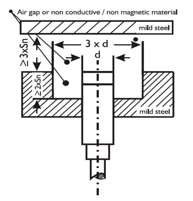
- Unshielded metal-free zone: clear a diameter of at least 3× the sensor diameter around the head, and keep the head proud of surrounding metal by at least 2× Sn.
- Side-by-side spacing: ≥ 2× diameter for shielded, ≥ 3× diameter for unshielded.
- Facing each other: ≥ 6× Sn for shielded, ≥ 12× Sn for unshielded.
What the shield actually does
Both types generate the field the same way — an oscillator drives a coil wound on a ferrite pot core. The difference is what surrounds that core.
In a shielded sensor, a copper or steel band wraps the circumference of the coil assembly. It absorbs the lateral component of the field and forces the flux to emerge only from the front. The result is a field shaped roughly like a short cylinder projecting from the face. Because energy that would have gone sideways is now dissipated in the shield, the forward reach is shorter — but the sensor is blind to metal beside it, so it can be threaded into a steel bracket right up to the face.
In an unshielded sensor, the core is open. The field balloons outward and forward, reaching further along the axis but also extending well past the barrel diameter. Surround that head with steel and the sensor sees the mounting, not the target, and latches permanently on.
Range comparison by thread size
Typical rated operating distances (Sn) for standard-range inductive sensors detecting mild steel:
| Thread size | Shielded Sn | Unshielded Sn | Gain |
|---|---|---|---|
| M8 | 1.5 mm | 2.5 mm | 1.7× |
| M12 | 2 mm | 4 mm | 2.0× |
| M18 | 5 mm | 8 mm | 1.6× |
| M30 | 10 mm | 15 mm | 1.5× |
Remember these are Sn figures. The distance you can actually design to is the assured operating distance, 0.81 Sn, further multiplied by the reduction factor for your target material. An unshielded M12 on aluminium gives 4 × 0.81 × 0.4 ≈ 1.3 mm, not 4 mm.
The metal-free zone, precisely
This is where most unshielded installations go wrong. Three separate clearances have to be satisfied:
1. Radial clearance around the head
Clear a circle of at least three times the sensor’s barrel diameter, centred on the sensing face. For an M18 unshielded sensor that means a 54 mm clear diameter — a 20 mm hole in a steel plate is nowhere near enough.
2. Axial protrusion from the mounting
The head must stand proud of surrounding metal by at least twice the rated operating distance. An unshielded M18 at Sn = 8 mm must project 16 mm beyond the bracket face.
3. Clearance to opposing metal
Any metal surface facing the sensor that is not the target must be at least three times Sn away. Machine guards, chute walls and tramp steel in the background all count.
If your mechanical design cannot give you all three, you do not have an unshielded application. Fit a shielded sensor and accept the shorter range, or move to a larger thread size.
Mutual interference between sensors
Two inductive sensors mounted close together can beat against each other. Their oscillators run at similar frequencies, the fields couple, and the result is an audible-frequency modulation that shows up as random chattering on both outputs. It is intermittent, it worsens as the units warm up, and it is very hard to diagnose if you do not know to look for it — it appears in our list of common proximity sensor faults for exactly that reason.
| Arrangement | Shielded minimum | Unshielded minimum |
|---|---|---|
| Side by side (centre to centre) | 2 × barrel diameter | 3 × barrel diameter |
| Facing each other | 6 × Sn | 12 × Sn |
| Opposed across a gap, same axis | Avoid — use a mechanical barrier or one sensor | Avoid |
Where the mechanical layout genuinely forces sensors closer than this, specify units with different oscillator frequencies, or use a design intended for tight arrays. Wiring them in series or parallel does not solve interference — that is a load and voltage-drop question, covered in our note on series and parallel connection of proximity switches.
Which to choose
| Situation | Choose | Why |
|---|---|---|
| Sensor threaded into a steel machine frame | Shielded | Only type that can sit flush without latching on |
| Detecting through a narrow slot or between fixtures | Shielded | Focused field ignores the surrounding fixture |
| End-of-stroke on a hydraulic cylinder | Shielded | Cylinder body is steel and close on all sides |
| Long gap to the target, open mounting | Unshielded | Range gain of 1.5–2× for the same thread size |
| Detecting non-ferrous targets at distance | Unshielded | Recovers range lost to the reduction factor |
| Sensor mounted on a plastic or aluminium bracket, clear space around | Unshielded | Metal-free zone is satisfied naturally |
| High-density sensor array | Shielded | Tighter spacing permitted, less mutual interference |
Semi-flush and other variants
Some ranges offer a semi-flush or “quasi-flush” option: partially shielded, mountable with a small recess, giving a range between the two extremes. It is a useful compromise when the drawing has already been cut and the metal-free zone is almost big enough. Treat the manufacturer’s stated mounting condition as binding — a semi-flush unit installed truly flush behaves like an unshielded one and will latch.
Once you have chosen the type, the mechanical installation still matters: tightening torque, locknut position and cable strain relief all affect long-term reliability. Those are covered in our guide to installing a proximity switch correctly.
Frequently asked questions
What happens if I mount an unshielded sensor flush in metal?
It detects the mounting bracket and its output latches permanently on, regardless of the target. The sensor is not damaged and will work normally once it is moved proud of the metal by at least twice its rated operating distance. This is the single most common commissioning fault with unshielded units.
Can a shielded sensor be mounted with the face recessed below the metal?
Slightly, but every millimetre of recess is subtracted from your working gap, and the surrounding metal begins to load the field once the recess approaches the sensing distance. Mount flush or very slightly proud. If the design needs a genuine recess, size the sensor for the recess depth plus the target gap.
Is an unshielded sensor always the better choice when I need more range?
Only if the metal-free zone can be met. If it cannot, a larger shielded sensor is the correct answer — an M30 shielded unit at 10 mm beats an M18 unshielded unit at 8 mm and mounts in metal. Compare the assured distance after material correction, not the headline figures.
Do these rules apply to capacitive sensors too?
The flush and non-flush distinction exists for capacitive sensors as well, and the mounting logic is the same. The clearances differ, and capacitive units are far more sensitive to build-up on the face and to surrounding dielectrics such as plastic guards, not just metal.
How do I know if my sensor is shielded or unshielded?
The datasheet states it directly, usually as “flush mountable” or “embeddable” versus “non-flush” or “non-embeddable”. Physically, unshielded sensors often have a sensing face that protrudes slightly as a plastic cap wider than the thread root, and their rated range is noticeably longer for the same thread size.
Working out whether your bracket allows a non-flush sensor? Send us the mounting drawing and the target details. Accent Controls builds flush and non-flush inductive proximity switches from M8 to M50 at our Mumbai plant, and our engineers will confirm the mounting condition before you commit to a design.