
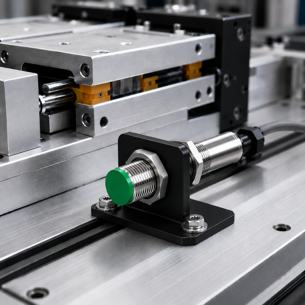
An inductive proximity switch is rated against mild steel. Put any other metal in front of it and the sensing distance falls. The reduction factor is the multiplier that tells you by how much: roughly 0.8 for stainless steel, 0.5 for brass, 0.4 for aluminium and 0.3 for copper. Multiply the rated distance by the factor before you set the mounting gap.
Quick reference
- The reference target in IEC 60947-5-2 is mild steel Fe360 (S235), 1 mm thick, square, with a side equal to the sensing face diameter or 3×Sn, whichever is larger.
- Reduction factor for that reference target is 1.0 by definition.
- Non-ferrous metals reduce the range because eddy-current losses in them couple less energy out of the oscillator.
- Targets thinner than 1 mm, smaller than the reference square, or with plating or coatings reduce it further.
- Factor 1 sensors hold the same range across all metals, at higher cost.
Why the sensing distance changes at all
An inductive sensor runs an LC oscillator that projects an alternating field from a ferrite core behind the sensing face. When a conductor enters that field, circulating eddy currents are induced in it. Those currents dissipate energy, the energy comes out of the oscillator, and its amplitude drops. The trigger stage watches for that drop.
How much energy a target absorbs depends on two of its properties. Permeability concentrates the field into the target; ferrous metals have high permeability and pull the field in strongly. Conductivity determines how readily eddy currents flow; copper and aluminium conduct extremely well, so the currents stay confined to a thin surface layer and dissipate comparatively little energy.
Mild steel wins on both counts — high permeability, moderate conductivity — which is why it is the reference. Copper, despite being the best conductor of the group, damps the oscillator least, and therefore gives the shortest sensing distance.
Typical reduction factors by material
| Target material | Typical reduction factor | Effective range on a 2 mm sensor |
|---|---|---|
| Mild steel (Fe360 / S235) — reference | 1.00 | 2.0 mm |
| Cast iron | 0.90 – 1.10 | 1.8 – 2.2 mm |
| Stainless steel, ferritic (430) | 0.85 – 0.95 | 1.7 – 1.9 mm |
| Stainless steel, austenitic (304 / 316, V2A / V4A) | 0.70 – 0.85 | 1.4 – 1.7 mm |
| Brass | 0.40 – 0.50 | 0.8 – 1.0 mm |
| Aluminium | 0.35 – 0.45 | 0.7 – 0.9 mm |
| Copper | 0.25 – 0.40 | 0.5 – 0.8 mm |
| Graphite | ≈ 0.30 | ≈ 0.6 mm |
These are typical values for standard inductive sensors and they vary between manufacturers, between sensor sizes and between oscillator designs. Treat the table as a design starting point and confirm against the datasheet for the part you are actually buying. Austenitic stainless in particular has a wide spread, because its permeability rises with cold working — a machined 316 target and a heavily formed 316 target will not read the same.
The other reductions nobody mentions
Material is only the first correction. Three more apply before you have a number you can mount to.
Target size
The reference target is a square whose side equals the sensing face diameter, or three times the rated operating distance, whichever is greater. A target smaller than that reduces the range roughly in proportion to the area presented. A 6 mm screw head in front of an M18 sensor may give you half the catalogue figure.
Target thickness
Below 1 mm, ferrous targets lose range because there is not enough material to carry the flux. Non-ferrous targets behave differently: very thin foil can actually give a longer range than thick stock of the same metal, because the eddy currents are forced into a resistive path and dissipate more energy. This is a genuine effect and a common source of confusion when commissioning foil and thin-sheet lines.
Plating and coating
Zinc, tin and chrome plating on a steel target changes the effective surface conductivity and typically costs 10–25% of range. Paint and powder coating do not absorb the field, but they add mechanical standoff — a 200 µm coating on a 0.8 mm working gap is a quarter of your margin gone.
From rated distance to a gap you can actually set
IEC 60947-5-2 defines four distances, and only one of them is safe to design against:
| Symbol | Name | Definition |
|---|---|---|
| Sn | Rated operating distance | The catalogue figure. A nominal value that excludes manufacturing tolerance, temperature and voltage effects. |
| Sr | Effective operating distance | Measured on one individual sensor at rated voltage and 23 °C. Permitted range 0.9 Sn to 1.1 Sn. |
| Su | Usable operating distance | Sr measured across the full temperature and supply-voltage range. Permitted range 0.81 Sn to 1.21 Sn. |
| Sa | Assured operating distance | 0 to 0.81 Sn. Detection is guaranteed anywhere in this band, for any unit, at any permitted temperature and voltage. |
So the honest working calculation is:
Working gap ≤ 0.81 × Sn × reduction factor
For an M18 sensor rated Sn = 8 mm detecting an aluminium bracket at reduction factor 0.4, that gives 8 × 0.81 × 0.4 = 2.6 mm. The catalogue said 8 mm. Designing to the catalogue figure is the single most common cause of intermittent sensors that pass at commissioning and fail in July when the panel runs hot.
When to reach for a Factor 1 sensor
Factor 1 sensors use a dual-coil arrangement and signal processing that compensates for the target material, giving essentially the same range on steel, stainless, aluminium and copper. They are worth the premium when:
- the line handles mixed materials and one sensor must detect all of them reliably;
- you are detecting aluminium or copper and cannot give up 60–75% of the range;
- the mechanical design fixes the gap and you cannot move the sensor closer;
- weld-field immunity matters, since many Factor 1 designs are also weld-immune.
Where the target material is known and constant — the overwhelming majority of machine building — a standard sensor one size up is usually cheaper and more robust than a Factor 1 unit of the original size.
Practical design rules
- Specify the target material on the drawing. “Detect the bracket” is not a specification. “Detect 3 mm 304 stainless, 30 × 30 mm face” is.
- Size the sensor from Sa, not Sn. Use the formula above and then leave mechanical tolerance on top of it.
- Add a mild-steel flag where you can. A small steel tab welded or bolted to an aluminium carriage restores the full range for a few rupees and removes the problem entirely.
- Check the mounting style. A non-flush (unshielded) sensor of the same thread size gives 1.5–2× the range of a flush one, which often recovers what the reduction factor took away — see our guide to shielded versus unshielded mounting.
- Verify at temperature. Set the gap, then confirm detection with the machine hot and the supply at its lower limit.
Frequently asked questions
What is the reduction factor for stainless steel?
Typically 0.7 to 0.85 for austenitic grades such as 304 and 316, and 0.85 to 0.95 for ferritic grades such as 430. Austenitic stainless varies with cold working, so a formed or machined component can read differently from bar stock of the same grade. Always confirm against the sensor datasheet.
Why does aluminium have a lower reduction factor than steel when it conducts better?
Because conductivity alone does not damp the oscillator. Aluminium has essentially no magnetic permeability, so it does not concentrate the field, and its high conductivity confines eddy currents to a thin, low-loss surface layer. Less energy is drawn from the oscillator, so the sensor detects it at a shorter distance.
Can I just mount the sensor closer to compensate?
Within limits, yes — that is exactly what the reduction factor calculation tells you to do. But you must not go below the mechanical clearance the application needs, and on a moving target you have to allow for vibration, thermal growth and wear. If the corrected assured distance leaves no practical gap, move up a sensor size or choose a Factor 1 unit.
Do reduction factors apply to capacitive sensors?
No. Capacitive sensors respond to the dielectric constant of the target, not its conductivity and permeability, so they use a different correction based on material dielectric. All metals look much the same to a capacitive sensor. See our guide to capacitive sensors for level detection.
Does the reduction factor change with temperature?
The factor itself is a material property and is essentially stable, but the sensing distance it multiplies is not. That temperature and voltage variation is exactly what the Su and Sa definitions account for, which is why you should design against 0.81 Sn rather than Sn.
Detecting something other than mild steel? Tell us the material, the target size and the gap you have available, and we will confirm the right sensor size and mounting style. Accent Controls manufactures inductive proximity switches from M8 to M50 in Mumbai, to IEC 60947-5-2.