Linear Position Transducers: Potentiometric vs LVDT vs Magnetostrictive

Three ways to measure linear position, compared on stroke, wear, environment and cost — plus the rotary equivalents and a six-point specification checklist.

Choose a potentiometric transducer when you want absolute position, a simple ratiometric output and low cost. Choose LVDT when you need a sealed, contactless element over a short stroke in a harsh or high-vibration environment. Choose magnetostrictive when the stroke is long, the duty is continuous, and wear is unacceptable — typically inside hydraulic cylinders.

Quick reference

  • Potentiometric — contact wiper on a conductive plastic track. Absolute, ratiometric, inexpensive, strokes from a few mm to over a metre.
  • LVDT — moving core in a transformer. Contactless element, excellent resolution, short to medium stroke, tolerant of shock.
  • Magnetostrictive — timed torsional pulse along a waveguide. Contactless, absolute, strokes to several metres, ideal in hydraulics.
  • All three give absolute position — no homing needed on power-up, unlike an incremental encoder.
  • Selection usually turns on stroke length, duty cycle and environment, not on accuracy.

How each technology works

Potentiometric

A wiper travels along a resistive track — in a quality industrial transducer, conductive plastic rather than wirewound. The output is a voltage divider: apply an excitation voltage across the track and read the wiper. Because the output is a fixed ratio of the excitation, drift in the supply cancels out, which is why potentiometric sensors are described as ratiometric and why they tolerate modest power supplies so well.

The wiper is a physical contact, so there is a wear mechanism. Modern conductive-plastic elements are rated for very large numbers of movements, and in most industrial duties the transducer outlives the machine. High-frequency dithering in one small part of the track is the case where wear genuinely bites.

LVDT

A linear variable differential transformer has one primary and two secondary windings, with a ferromagnetic core free to move inside. The primary is excited with AC; the two secondaries are wired in opposition. With the core centred their outputs cancel. As it moves, one secondary dominates, and the amplitude and phase of the difference give position.

The core does not touch the windings, so there is nothing to wear. The winding assembly can be fully sealed and even hermetically welded, and the whole device is essentially insensitive to shock and vibration. Resolution is limited only by the electronics, which is why LVDTs remain standard in test rigs and aerospace.

Magnetostrictive

A current pulse is launched down a magnetostrictive waveguide. A permanent magnet, carried on the moving element, sits somewhere along that waveguide. Where the pulse’s field meets the magnet’s field, a torsional strain wave is generated and travels back to a pickup at the head. Measure the time of flight, multiply by the known wave velocity, and you have absolute position.

Nothing touches. The magnet can be separated from the waveguide by a non-magnetic barrier, which is why these sensors can be installed inside a hydraulic cylinder through a gun-drilled rod, with the rod itself acting as the pressure boundary.

Direct comparison

  Potentiometric LVDT Magnetostrictive
Contact Wiper on track None None
Typical stroke 10 mm – 1 m+ 1 mm – 500 mm 50 mm – several metres
Absolute output Yes Yes Yes
Output type Ratiometric voltage; conditioned 0–10 V / 4–20 mA versions available AC differential, or DC with built-in conditioning Analogue, SSI, CANopen, IO-Link and others
Wear mechanism Wiper and track Bearings only, if fitted None in the sensing path
Vibration tolerance Good Excellent Very good
Suits hydraulic cylinder installation Rarely Occasionally Yes — the standard solution
Relative cost Low Medium to high High
Electronics required Minimal Oscillator and demodulator Integrated, always

Choosing by application

Application Usual choice Reason
Injection moulding — screw and clamp position Potentiometric or magnetostrictive Long stroke, continuous cycling; magnetostrictive where duty is extreme
Hydraulic cylinder feedback Magnetostrictive Mounts inside the cylinder; no seal to fail on a moving rod
Valve and actuator position Potentiometric Short stroke, low duty, cost matters
Materials test rig LVDT Resolution and shock tolerance outweigh cost
Aerospace control surface LVDT Sealed, contactless, proven in the sector
Packaging machine format adjustment Potentiometric Infrequent movement, absolute readout on power-up
Steel mill roll gap Magnetostrictive or LVDT Environment and duty rule out contact devices
Machine tool axis Neither — use a linear encoder Micron-level accuracy over long travel

Rotary equivalents

The same logic applies to angular measurement. A rotary single-turn sensor covers up to 360° and suits throttle, damper and valve positions. Where the shaft turns through many revolutions — a screw jack, a cable drum, a steering column — a rotary multi-turn sensor keeps an absolute count across the whole travel, so position is known immediately on power-up with no homing move.

Contactless rotary sensors using Hall-effect or inductive principles have largely displaced potentiometric rotary units in high-cycle duties, for exactly the wear reasons described above.

Specification checklist

  1. Stroke and mounting length. The installed length always exceeds the electrical stroke. Confirm the mechanical envelope before selecting.
  2. Linearity you actually need. Independent linearity is usually quoted as a percentage of full stroke; over a long stroke a good percentage is still a large absolute error. Ask for the number in millimetres.
  3. Duty cycle. Movements per day, and whether the motion concentrates in one part of the stroke. This decides whether a contact device is acceptable.
  4. Output interface. Match the controller: ratiometric voltage, 0–10 V, 4–20 mA, SSI, CANopen or IO-Link. Retrofits usually dictate this.
  5. Environment. Temperature, vibration, ingress and any chemical exposure — see our guide to IP ratings and what each test proves.
  6. Coupling. A rigid coupling between machine and transducer transmits misalignment straight into the element and shortens its life. Use the specified ball joint or flexible coupling.

Accent Controls is the sole authorised distributor in India and SAARC for Novotechnik of Germany and Contelec of Switzerland, alongside the proximity and photoelectric sensors we manufacture in Mumbai. That means we can specify contact and contactless position measurement from the same conversation — see our overview of position sensor solutions.

Frequently asked questions

What is the difference between a linear transducer and a linear encoder?

A transducer of the types described here gives an absolute analogue or digital position over its stroke, typically at millimetre to sub-millimetre resolution, and needs no homing on power-up. A linear encoder — usually optical or magnetic scale — targets much finer resolution over machine-tool travels and is often incremental, requiring a reference move after power-up. They solve different problems at different price points.

Do potentiometric transducers wear out?

The wiper and track are a contact pair, so yes in principle. In practice a good conductive-plastic element is rated for a very large number of movements and outlasts the machine in most industrial duties. The exception is high-frequency dithering concentrated in one small region of the stroke, which wears a localised flat and shows up as noise at that position — a contactless technology is the right answer there.

Can a magnetostrictive sensor be fitted inside a hydraulic cylinder?

Yes, and it is the standard solution for cylinder position feedback. The waveguide is installed in a gun-drilled bore in the piston rod, with the position magnet on the piston. Nothing penetrates the pressure boundary and there is no dynamic seal on a moving sensor element, which is exactly why the arrangement is so reliable.

Which is most accurate?

LVDTs generally offer the best resolution and repeatability over short strokes, because resolution is limited by the electronics rather than by any physical division. Over long strokes magnetostrictive devices are usually the most accurate in absolute terms. But for most industrial applications repeatability and long-term stability matter more than headline accuracy — specify what the machine needs rather than the best number available.

Do I need a linear transducer or would proximity switches do?

If you only need to know that the axis has reached a small number of fixed positions, proximity switches are simpler, cheaper and more robust — see our inductive proximity switch range. A transducer is warranted when you need continuous position, when the target positions change with the product format, or when the controller closes a loop on position.

Selecting position measurement for a machine? Tell us the stroke, the duty cycle, the controller interface and the environment. As the authorised Novotechnik and Contelec distributor for India and SAARC, Accent Controls can quote potentiometric, LVDT-class and contactless options side by side.

Discuss a position sensor Linear position transducers About Accent Controls
Shielded vs Unshielded Inductive Sensors: Flush Mounting, Spacing and Metal-Free Zones

Flush or non-flush? Range by thread size, the three clearances an unshielded sensor needs, and the spacing rules that stop adjacent sensors chattering.

A shielded (flush) inductive sensor has a metal band around its coil that confines the field to the front face, so it can be buried level with a steel bracket. An unshielded (non-flush) sensor lets the field spread sideways, giving 1.5–2× the sensing range but demanding a metal-free zone around the head.

Quick reference

  • Shielded — mounts flush in metal. Shorter range. Narrow, focused field.
  • Unshielded — must project above the metal. Longer range. Wider field.
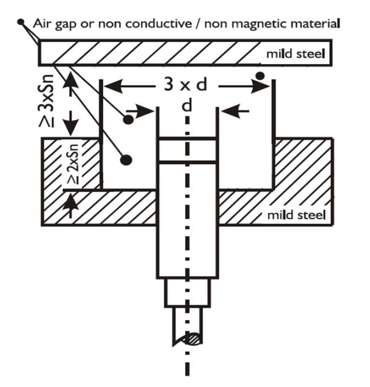
  • Unshielded metal-free zone: clear a diameter of at least 3× the sensor diameter around the head, and keep the head proud of surrounding metal by at least 2× Sn.
  • Side-by-side spacing: ≥ 2× diameter for shielded, ≥ 3× diameter for unshielded.
  • Facing each other: ≥ 6× Sn for shielded, ≥ 12× Sn for unshielded.

What the shield actually does

Both types generate the field the same way — an oscillator drives a coil wound on a ferrite pot core. The difference is what surrounds that core.

In a shielded sensor, a copper or steel band wraps the circumference of the coil assembly. It absorbs the lateral component of the field and forces the flux to emerge only from the front. The result is a field shaped roughly like a short cylinder projecting from the face. Because energy that would have gone sideways is now dissipated in the shield, the forward reach is shorter — but the sensor is blind to metal beside it, so it can be threaded into a steel bracket right up to the face.

In an unshielded sensor, the core is open. The field balloons outward and forward, reaching further along the axis but also extending well past the barrel diameter. Surround that head with steel and the sensor sees the mounting, not the target, and latches permanently on.

Range comparison by thread size

Typical rated operating distances (Sn) for standard-range inductive sensors detecting mild steel:

Thread size Shielded Sn Unshielded Sn Gain
M8 1.5 mm 2.5 mm 1.7×
M12 2 mm 4 mm 2.0×
M18 5 mm 8 mm 1.6×
M30 10 mm 15 mm 1.5×

Remember these are Sn figures. The distance you can actually design to is the assured operating distance, 0.81 Sn, further multiplied by the reduction factor for your target material. An unshielded M12 on aluminium gives 4 × 0.81 × 0.4 ≈ 1.3 mm, not 4 mm.

The metal-free zone, precisely

This is where most unshielded installations go wrong. Three separate clearances have to be satisfied:

1. Radial clearance around the head

Clear a circle of at least three times the sensor’s barrel diameter, centred on the sensing face. For an M18 unshielded sensor that means a 54 mm clear diameter — a 20 mm hole in a steel plate is nowhere near enough.

2. Axial protrusion from the mounting

The head must stand proud of surrounding metal by at least twice the rated operating distance. An unshielded M18 at Sn = 8 mm must project 16 mm beyond the bracket face.

3. Clearance to opposing metal

Any metal surface facing the sensor that is not the target must be at least three times Sn away. Machine guards, chute walls and tramp steel in the background all count.

If your mechanical design cannot give you all three, you do not have an unshielded application. Fit a shielded sensor and accept the shorter range, or move to a larger thread size.

Mutual interference between sensors

Two inductive sensors mounted close together can beat against each other. Their oscillators run at similar frequencies, the fields couple, and the result is an audible-frequency modulation that shows up as random chattering on both outputs. It is intermittent, it worsens as the units warm up, and it is very hard to diagnose if you do not know to look for it — it appears in our list of common proximity sensor faults for exactly that reason.

Arrangement Shielded minimum Unshielded minimum
Side by side (centre to centre) 2 × barrel diameter 3 × barrel diameter
Facing each other 6 × Sn 12 × Sn
Opposed across a gap, same axis Avoid — use a mechanical barrier or one sensor Avoid

Where the mechanical layout genuinely forces sensors closer than this, specify units with different oscillator frequencies, or use a design intended for tight arrays. Wiring them in series or parallel does not solve interference — that is a load and voltage-drop question, covered in our note on series and parallel connection of proximity switches.

Which to choose

Situation Choose Why
Sensor threaded into a steel machine frame Shielded Only type that can sit flush without latching on
Detecting through a narrow slot or between fixtures Shielded Focused field ignores the surrounding fixture
End-of-stroke on a hydraulic cylinder Shielded Cylinder body is steel and close on all sides
Long gap to the target, open mounting Unshielded Range gain of 1.5–2× for the same thread size
Detecting non-ferrous targets at distance Unshielded Recovers range lost to the reduction factor
Sensor mounted on a plastic or aluminium bracket, clear space around Unshielded Metal-free zone is satisfied naturally
High-density sensor array Shielded Tighter spacing permitted, less mutual interference

Semi-flush and other variants

Some ranges offer a semi-flush or “quasi-flush” option: partially shielded, mountable with a small recess, giving a range between the two extremes. It is a useful compromise when the drawing has already been cut and the metal-free zone is almost big enough. Treat the manufacturer’s stated mounting condition as binding — a semi-flush unit installed truly flush behaves like an unshielded one and will latch.

Once you have chosen the type, the mechanical installation still matters: tightening torque, locknut position and cable strain relief all affect long-term reliability. Those are covered in our guide to installing a proximity switch correctly.

Frequently asked questions

What happens if I mount an unshielded sensor flush in metal?

It detects the mounting bracket and its output latches permanently on, regardless of the target. The sensor is not damaged and will work normally once it is moved proud of the metal by at least twice its rated operating distance. This is the single most common commissioning fault with unshielded units.

Can a shielded sensor be mounted with the face recessed below the metal?

Slightly, but every millimetre of recess is subtracted from your working gap, and the surrounding metal begins to load the field once the recess approaches the sensing distance. Mount flush or very slightly proud. If the design needs a genuine recess, size the sensor for the recess depth plus the target gap.

Is an unshielded sensor always the better choice when I need more range?

Only if the metal-free zone can be met. If it cannot, a larger shielded sensor is the correct answer — an M30 shielded unit at 10 mm beats an M18 unshielded unit at 8 mm and mounts in metal. Compare the assured distance after material correction, not the headline figures.

Do these rules apply to capacitive sensors too?

The flush and non-flush distinction exists for capacitive sensors as well, and the mounting logic is the same. The clearances differ, and capacitive units are far more sensitive to build-up on the face and to surrounding dielectrics such as plastic guards, not just metal.

How do I know if my sensor is shielded or unshielded?

The datasheet states it directly, usually as “flush mountable” or “embeddable” versus “non-flush” or “non-embeddable”. Physically, unshielded sensors often have a sensing face that protrudes slightly as a plastic cap wider than the thread root, and their rated range is noticeably longer for the same thread size.

Working out whether your bracket allows a non-flush sensor? Send us the mounting drawing and the target details. Accent Controls builds flush and non-flush inductive proximity switches from M8 to M50 at our Mumbai plant, and our engineers will confirm the mounting condition before you commit to a design.

Check my mounting Browse inductive sensors

Inductive Sensor Reduction Factors: Steel, Stainless, Aluminium, Brass and Copper

Sensing distance falls on every metal except mild steel. The reduction factor table, the three corrections nobody mentions, and how to get to a real mounting gap.

An inductive proximity switch is rated against mild steel. Put any other metal in front of it and the sensing distance falls. The reduction factor is the multiplier that tells you by how much: roughly 0.8 for stainless steel, 0.5 for brass, 0.4 for aluminium and 0.3 for copper. Multiply the rated distance by the factor before you set the mounting gap.

Quick reference

  • The reference target in IEC 60947-5-2 is mild steel Fe360 (S235), 1 mm thick, square, with a side equal to the sensing face diameter or 3×Sn, whichever is larger.
  • Reduction factor for that reference target is 1.0 by definition.
  • Non-ferrous metals reduce the range because eddy-current losses in them couple less energy out of the oscillator.
  • Targets thinner than 1 mm, smaller than the reference square, or with plating or coatings reduce it further.
  • Factor 1 sensors hold the same range across all metals, at higher cost.

Why the sensing distance changes at all

An inductive sensor runs an LC oscillator that projects an alternating field from a ferrite core behind the sensing face. When a conductor enters that field, circulating eddy currents are induced in it. Those currents dissipate energy, the energy comes out of the oscillator, and its amplitude drops. The trigger stage watches for that drop.

How much energy a target absorbs depends on two of its properties. Permeability concentrates the field into the target; ferrous metals have high permeability and pull the field in strongly. Conductivity determines how readily eddy currents flow; copper and aluminium conduct extremely well, so the currents stay confined to a thin surface layer and dissipate comparatively little energy.

Mild steel wins on both counts — high permeability, moderate conductivity — which is why it is the reference. Copper, despite being the best conductor of the group, damps the oscillator least, and therefore gives the shortest sensing distance.

Typical reduction factors by material

Target material Typical reduction factor Effective range on a 2 mm sensor
Mild steel (Fe360 / S235) — reference 1.00 2.0 mm
Cast iron 0.90 – 1.10 1.8 – 2.2 mm
Stainless steel, ferritic (430) 0.85 – 0.95 1.7 – 1.9 mm
Stainless steel, austenitic (304 / 316, V2A / V4A) 0.70 – 0.85 1.4 – 1.7 mm
Brass 0.40 – 0.50 0.8 – 1.0 mm
Aluminium 0.35 – 0.45 0.7 – 0.9 mm
Copper 0.25 – 0.40 0.5 – 0.8 mm
Graphite ≈ 0.30 ≈ 0.6 mm

These are typical values for standard inductive sensors and they vary between manufacturers, between sensor sizes and between oscillator designs. Treat the table as a design starting point and confirm against the datasheet for the part you are actually buying. Austenitic stainless in particular has a wide spread, because its permeability rises with cold working — a machined 316 target and a heavily formed 316 target will not read the same.

The other reductions nobody mentions

Material is only the first correction. Three more apply before you have a number you can mount to.

Target size

The reference target is a square whose side equals the sensing face diameter, or three times the rated operating distance, whichever is greater. A target smaller than that reduces the range roughly in proportion to the area presented. A 6 mm screw head in front of an M18 sensor may give you half the catalogue figure.

Target thickness

Below 1 mm, ferrous targets lose range because there is not enough material to carry the flux. Non-ferrous targets behave differently: very thin foil can actually give a longer range than thick stock of the same metal, because the eddy currents are forced into a resistive path and dissipate more energy. This is a genuine effect and a common source of confusion when commissioning foil and thin-sheet lines.

Plating and coating

Zinc, tin and chrome plating on a steel target changes the effective surface conductivity and typically costs 10–25% of range. Paint and powder coating do not absorb the field, but they add mechanical standoff — a 200 µm coating on a 0.8 mm working gap is a quarter of your margin gone.

From rated distance to a gap you can actually set

IEC 60947-5-2 defines four distances, and only one of them is safe to design against:

Symbol Name Definition
Sn Rated operating distance The catalogue figure. A nominal value that excludes manufacturing tolerance, temperature and voltage effects.
Sr Effective operating distance Measured on one individual sensor at rated voltage and 23 °C. Permitted range 0.9 Sn to 1.1 Sn.
Su Usable operating distance Sr measured across the full temperature and supply-voltage range. Permitted range 0.81 Sn to 1.21 Sn.
Sa Assured operating distance 0 to 0.81 Sn. Detection is guaranteed anywhere in this band, for any unit, at any permitted temperature and voltage.

So the honest working calculation is:

Working gap ≤ 0.81 × Sn × reduction factor

For an M18 sensor rated Sn = 8 mm detecting an aluminium bracket at reduction factor 0.4, that gives 8 × 0.81 × 0.4 = 2.6 mm. The catalogue said 8 mm. Designing to the catalogue figure is the single most common cause of intermittent sensors that pass at commissioning and fail in July when the panel runs hot.

When to reach for a Factor 1 sensor

Factor 1 sensors use a dual-coil arrangement and signal processing that compensates for the target material, giving essentially the same range on steel, stainless, aluminium and copper. They are worth the premium when:

  • the line handles mixed materials and one sensor must detect all of them reliably;
  • you are detecting aluminium or copper and cannot give up 60–75% of the range;
  • the mechanical design fixes the gap and you cannot move the sensor closer;
  • weld-field immunity matters, since many Factor 1 designs are also weld-immune.

Where the target material is known and constant — the overwhelming majority of machine building — a standard sensor one size up is usually cheaper and more robust than a Factor 1 unit of the original size.

Practical design rules

  1. Specify the target material on the drawing. “Detect the bracket” is not a specification. “Detect 3 mm 304 stainless, 30 × 30 mm face” is.
  2. Size the sensor from Sa, not Sn. Use the formula above and then leave mechanical tolerance on top of it.
  3. Add a mild-steel flag where you can. A small steel tab welded or bolted to an aluminium carriage restores the full range for a few rupees and removes the problem entirely.
  4. Check the mounting style. A non-flush (unshielded) sensor of the same thread size gives 1.5–2× the range of a flush one, which often recovers what the reduction factor took away — see our guide to shielded versus unshielded mounting.
  5. Verify at temperature. Set the gap, then confirm detection with the machine hot and the supply at its lower limit.

Frequently asked questions

What is the reduction factor for stainless steel?

Typically 0.7 to 0.85 for austenitic grades such as 304 and 316, and 0.85 to 0.95 for ferritic grades such as 430. Austenitic stainless varies with cold working, so a formed or machined component can read differently from bar stock of the same grade. Always confirm against the sensor datasheet.

Why does aluminium have a lower reduction factor than steel when it conducts better?

Because conductivity alone does not damp the oscillator. Aluminium has essentially no magnetic permeability, so it does not concentrate the field, and its high conductivity confines eddy currents to a thin, low-loss surface layer. Less energy is drawn from the oscillator, so the sensor detects it at a shorter distance.

Can I just mount the sensor closer to compensate?

Within limits, yes — that is exactly what the reduction factor calculation tells you to do. But you must not go below the mechanical clearance the application needs, and on a moving target you have to allow for vibration, thermal growth and wear. If the corrected assured distance leaves no practical gap, move up a sensor size or choose a Factor 1 unit.

Do reduction factors apply to capacitive sensors?

No. Capacitive sensors respond to the dielectric constant of the target, not its conductivity and permeability, so they use a different correction based on material dielectric. All metals look much the same to a capacitive sensor. See our guide to capacitive sensors for level detection.

Does the reduction factor change with temperature?

The factor itself is a material property and is essentially stable, but the sensing distance it multiplies is not. That temperature and voltage variation is exactly what the Su and Sa definitions account for, which is why you should design against 0.81 Sn rather than Sn.

Detecting something other than mild steel? Tell us the material, the target size and the gap you have available, and we will confirm the right sensor size and mounting style. Accent Controls manufactures inductive proximity switches from M8 to M50 in Mumbai, to IEC 60947-5-2.

Get a sizing check Browse inductive sensors