

Capacitive Proximity Sensors for Level Detection: Sensing Through Tank Walls

Capacitive sensors respond to dielectric constant, so they read water through a plastic tank wall. The materials table, the setup procedure, and the failure modes.

A capacitive proximity sensor detects anything with a dielectric constant higher than air — water, oil, plastic granules, powder, grain, glass. That is why it can be strapped to the outside of a non-metallic tank and sense the liquid through the wall, something an inductive sensor can never do.

Quick reference

  • Senses dielectric change, not conductivity — so it detects metals and non-metals alike.
  • Water (εr ≈ 80) is easy. Dry plastic granules (εr ≈ 2–3) are hard.
  • Through-wall sensing works on plastic or glass walls up to roughly 4–10 mm, depending on sensor size.
  • Sensing distance is typically 1–25 mm depending on thread size and target dielectric.
  • The main enemy is build-up on the face, followed by condensation and foam.

How dielectric sensing works

The sensing face of a capacitive sensor is one plate of a capacitor; the machine frame and surroundings form the other. An oscillator drives that capacitance. Bring any material with a dielectric constant higher than air into the field and the capacitance rises, the oscillator amplitude changes, and the trigger stage switches.

Because the mechanism is dielectric rather than eddy-current, there is no distinction between ferrous and non-ferrous, and no reduction factor table for metals as there is with inductive sensors. What matters instead is the dielectric constant of whatever you are trying to detect.

Dielectric constants of common process materials

Material Relative dielectric constant (εr) Ease of detection
Air / vacuum 1.0 Reference — not detected
PTFE ≈ 2.0 Difficult
Polypropylene, polyethylene 2.0 – 2.3 Difficult
Dry paper, cardboard 2 – 4 Difficult
Mineral and hydraulic oil 2 – 4 Moderate
Nylon, PVC, acrylic 3 – 5 Moderate
Glass, quartz 3.7 – 10 Moderate
Wood (dry to damp) 2 – 7 Varies with moisture
Flour, sugar, cement powder 3 – 10 Moderate — varies with packing density
Alcohols 16 – 33 Easy
Water, aqueous solutions ≈ 80 Very easy
Any metal Effectively infinite Very easy — detected at maximum range

The practical consequence: anything water-based is straightforward, dry plastics are the hard case. If you are detecting polypropylene pellets in a hopper you are working at εr ≈ 2, which is only twice air, and you should expect to need a larger sensor, a shorter gap and careful sensitivity setting.

Sensing level through a tank wall

This is the capacitive sensor’s signature application. Mount the sensor on the outside of a non-conductive tank at the level you want to monitor. The wall is part of the dielectric path; the sensor’s field passes through it and responds to what is on the far side.

It works when three conditions hold:

  1. The wall is non-conductive — plastic, glass, ceramic. A metal tank shields the field completely and the sensor will only ever see the wall.
  2. The wall is thin enough. As a rule of thumb, wall thickness must be well inside the sensor’s rated sensing distance, since the wall consumes part of it. Small sensors manage 2–4 mm; larger M30 units with 20 mm+ range can handle 8–10 mm walls, but only for a high-dielectric medium like water.
  3. There is a clear dielectric step between “full” and “empty” at that point. Water against plastic gives a very large step. Oil against plastic gives a modest one. Dry powder against plastic gives a small one.

Setting it up

The reliable procedure is to set the threshold with the tank empty at that level, not full:

  1. Fit the sensor firmly against the wall with no air gap — an air gap between sensor face and wall is wasted sensing distance. Use the supplied bracket or a bonded pad.
  2. With the level below the sensor, turn the sensitivity up until the sensor just operates on the empty wall, then back it off until it releases.
  3. Back it off a further margin — typically 10–20% of the adjustment range.
  4. Fill above the sensor and confirm solid operation with margin.
  5. Cycle the level several times, and check again after the tank has been through a full thermal cycle.

What goes wrong, and what to do about it

Symptom Likely cause Fix
Output stays on after level drops Product clinging to the inside of the wall, or build-up on the sensor face Reduce sensitivity; move to a location with flow across it; specify a build-up-resistant variant
Chatters near the switch point Insufficient hysteresis for a slow-moving, turbulent or foaming level Choose a unit with greater hysteresis; add a short off-delay in the PLC; fit a stilling arrangement
Trips when an operator walks past Sensitivity set far too high — the sensor is seeing the room Reduce sensitivity; the correct setting operates on product, not on ambient
Works in the morning, fails by afternoon Condensation on the outside of a chilled tank, or thermal drift Shield and insulate the sensing area; set the threshold at worst-case temperature
Never detects the product Dielectric constant too low, wall too thick, or metallic tank Move up a sensor size, sense through a plastic sight tube, or change technology
Erratic on a metal tank The tank is shielding the field Capacitive is the wrong choice — use an internal probe, a level switch, or an external ultrasonic device

Mounting rules

Capacitive sensors follow the same flush and non-flush logic as inductive units, but they are more sensitive to their surroundings because any dielectric affects them, not just metal. A plastic guard 20 mm from a non-flush capacitive sensor is not neutral the way it would be for an inductive one.

  • Flush (shielded) units can be embedded in metal and are the right default for tank-wall and machine-mounted duties.
  • Non-flush units reach further but need a metal-free and dielectric-free zone around the head.
  • Side-by-side spacing should be at least twice the barrel diameter, more for non-flush units — the same principle described in our guide to shielded versus unshielded mounting.
  • Keep cable runs short and away from VFD power cables. Capacitive front ends are high-impedance and pick up electrical noise readily.

Capacitive or something else?

Application Best choice
Metal target, dirty environment, need robustness Inductive
Liquid level through a plastic tank wall Capacitive
Powder or granule level in a plastic or glass hopper Capacitive, sized generously
Detecting product inside a sealed metal vessel Not capacitive — use an internal probe or ultrasonic
Presence of a box or label at a distance Photoelectric — see fundamentals of photoelectric sensing
Detecting through a stainless steel cylinder wall Magnetic, with a magnet on the piston
Continuous level measurement, not a switch point Radar, ultrasonic or hydrostatic — capacitive proximity is a switch, not a transmitter

Frequently asked questions

Can a capacitive sensor detect water through a plastic tank?

Yes, and it is one of the most reliable capacitive applications there is. Water’s dielectric constant of about 80 gives an enormous signal step against an empty wall. Practical limits are wall thickness relative to the sensor’s rated range, and product clinging to the inside of the wall after the level drops.

Will it work through a metal tank wall?

No. A conductive wall completely shields the electric field, so the sensor responds only to the wall itself. For metal vessels you need an internal probe, a float or paddle switch, or a non-contact technology such as radar or ultrasonic mounted through a nozzle.

Why does my capacitive sensor stay on after the tank empties?

Almost always product residue on the inside of the wall, or build-up on the sensor face. The sensor is doing exactly what it should — there is still high-dielectric material in its field. Reduce sensitivity so it needs bulk product rather than a film, and if possible relocate to a point where the product flows past rather than sits.

What is the maximum sensing distance?

Typically 1 to 25 mm depending on thread size, mounting style and the target’s dielectric constant. The catalogue figure is quoted against an earthed metal target, which is the easiest possible case. Detecting dry plastic granules you should expect a fraction of that, so size the sensor from the real target, not the headline number.

Can I use one to detect a plastic part on a conveyor?

Yes, if the part is close and reasonably substantial. Thin dry plastic at εr ≈ 2 is a hard target, and a moving belt of varying moisture content is a shifting background. For general presence detection on a conveyor, a photoelectric sensor is usually more repeatable — our guide to selecting the right photoelectric switch type covers the options.

Have a level or non-metallic detection problem? Tell us the material, the wall construction and thickness, and the switch point you need. Accent Controls manufactures capacitive proximity switches in Mumbai and our engineers will tell you honestly whether capacitive is the right technology for the job.
Ask an engineer Browse capacitive sensors

Hot Metal Detectors for Rolling Mills: How HMDs Work and Where to Mount Them

HMDs see the infrared that hot steel emits, so they need no emitter across the pass line. What mills use them for, and the five mounting rules that decide reliability.

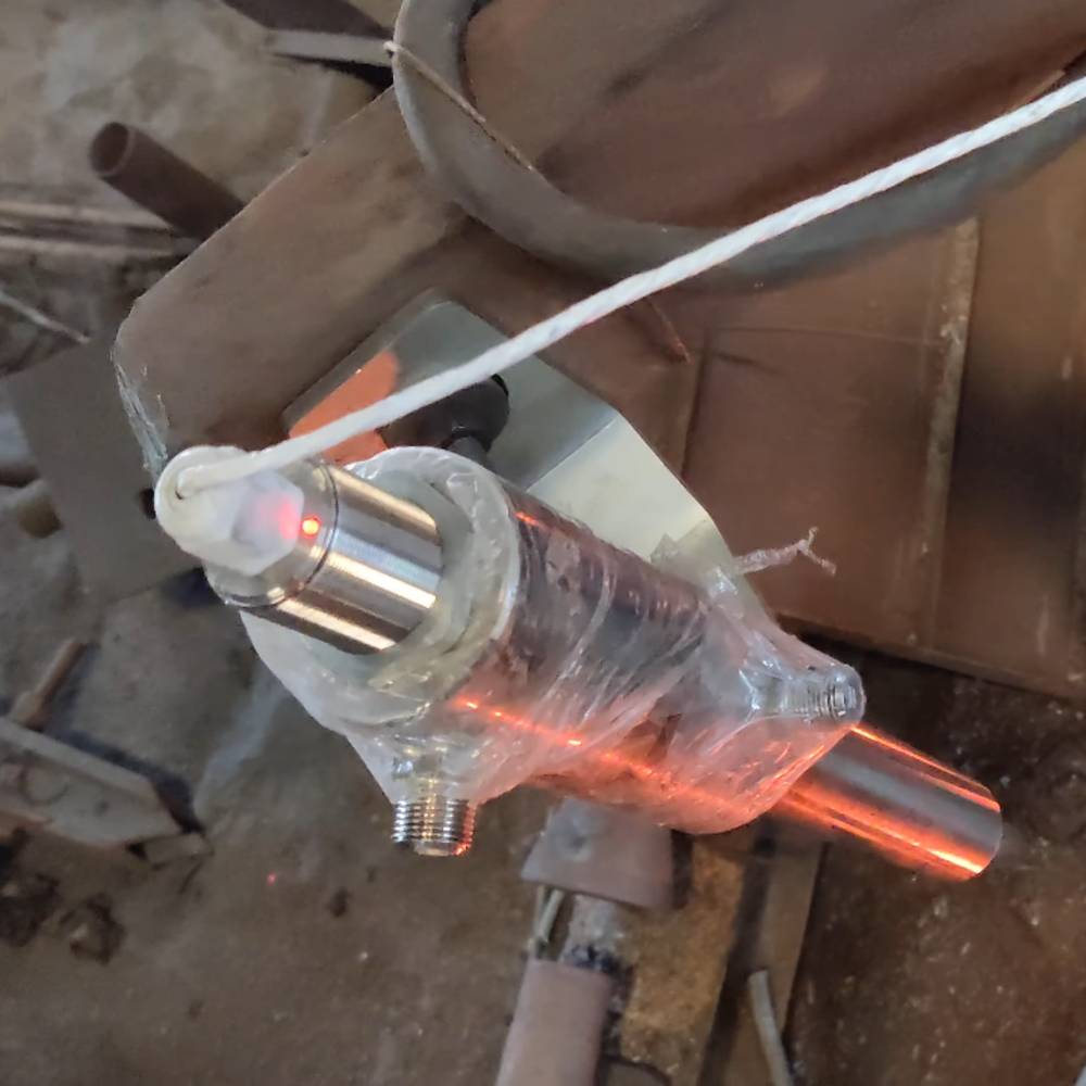
A hot metal detector (HMD) is a non-contact sensor that sees the infrared radiation emitted by hot steel and outputs a switching signal the moment a bar, billet or slab enters its field of view. Rolling mills use them to sequence stands, trigger shears, protect equipment and start timers — because at 700–1200 °C nothing mechanical survives near the pass line.

Quick reference

  • Detects emitted infrared — no emitter, no reflector, no contact with the stock.
  • Typical detection threshold from around 600–700 °C upward, adjustable by sensitivity setting.
  • Response time in the low milliseconds, fast enough for high-speed rod and wire mills.
  • Mounted off the pass line, sighting through a gap, with air purge and often water cooling.
  • Main duties: stand-to-stand sequencing, shear triggering, cobble detection, loop control, mill-protection interlocks.

How a hot metal detector works

Every object above absolute zero radiates energy, and the hotter it gets the more it radiates and the shorter the peak wavelength becomes. Steel at rolling temperature — 900 °C to 1200 °C for most long-product mills — radiates strongly in the near and short-wave infrared.

An HMD is essentially a filtered infrared receiver with a lens and a threshold detector. Its optics define a narrow cone of view aimed across the pass line. Ambient mill structure, cool rolls and the housing itself radiate far too little at those wavelengths to register. When hot stock crosses the cone, the received energy jumps by orders of magnitude, crosses the threshold, and the output switches.

Two design decisions matter in practice:

  • Spectral band. Narrowing the band to the short-wave infrared makes the detector far less sensitive to steam, water spray and scale dust, all of which are unavoidable around a mill.
  • Field of view. A tight cone gives a crisp leading-edge signal and precise timing. A wide cone is more tolerant of stock wander but blurs the switching point.

Because it is a passive receiver, an HMD needs nothing on the other side of the pass line. That single fact is why it displaced through-beam photoelectric arrangements in mills: there is no emitter to align, nothing to be destroyed by a cobble, and no lens on the far side to keep clean.

What HMDs are used for in a rolling mill

Duty What the HMD does Why it matters
Stand sequencing Signals bar arrival at each stand entry Starts the next stand at the right instant; prevents stand-to-stand tension errors
Shear triggering Marks the leading edge for crop-cut timing Crop length accuracy directly drives yield; a few milliseconds is several centimetres of steel
Cobble detection Absence of expected signal within a time window Stops the mill before a cobble wraps a roll or fills a guide
Loop control Confirms stock presence in the looper zone Enables tension-free rolling and dimensional consistency
Furnace discharge Confirms billet has left the furnace Interlocks pusher and roller table sequence
Cooling bed transfer Counts and positions bars Automates transfer without operators near hot stock
Roller table control Presence and direction of travel Reversing mill sequencing, table speed changes

Two HMDs a known distance apart on the same table also give you a speed measurement for free: divide the separation by the time between leading-edge signals. Many mills use this as a sanity check against the drive encoder.

Mounting: where installations go wrong

An HMD is a simple device that fails almost entirely for installation reasons. Five rules cover most of it.

Sight across the pass line, not along it

Aim the cone perpendicular to travel so the leading edge produces a sharp transition. Sighting at a shallow angle along the direction of travel smears the switching point over a long distance and destroys timing accuracy.

Keep it out of the heat, and cool it anyway

Mount off the pass line behind structure wherever possible, sighting through a gap in guarding. Even then, the ambient near a hot mill will exceed the electronics rating. A water-cooled housing is standard practice on stands and near the furnace; on cooler parts of the line an air-cooled jacket may suffice. Check the housing rating against the actual measured ambient, not the nominal one.

Air purge the lens, always

Scale dust and oil mist will coat the optics within days. A continuous clean, dry air purge across the lens face is not optional — it is the difference between a sensor that runs for years and one that needs weekly cleaning. Feed it from an instrument air supply with a filter and, ideally, a flow switch that alarms if purge is lost.

Control the background

The cone must not see another hot object behind the target. A second strand, an adjacent furnace door, or a glowing roll in the background will hold the output on permanently. Add a physical baffle or shield behind the sight line where the geometry allows.

Plan for cobbles

Assume the mounting will one day be struck by tangled stock. Fit the head behind a sacrificial guard, run the cable in armoured conduit away from the pass line, and keep a spare on the shelf. In a mill, mean time to repair matters more than mean time between failures.

Setting sensitivity

Sensitivity sets the effective temperature threshold. Set it too high and cooler tail ends of the bar are missed — which shows up as intermittent faults at the end of a rolling campaign as the furnace drifts. Set it too low and the detector picks up hot scale on the table, radiant heat from adjacent equipment, or its own reflections off polished guarding.

The practical method:

  1. Run the mill and observe the signal margin with hot stock in view — you want a large, unambiguous swing, not a marginal trip.
  2. Observe the signal with the pass line clear but the mill hot, including immediately after a bar has passed.
  3. Set the threshold in the middle of that gap, then verify at the coolest stock you expect to roll, not the hottest.
  4. Re-check after a shift, once the housing has reached its steady-state temperature.

Where HMDs fit alongside other sensing

A rolling mill needs more than hot-metal detection. Cold stock at the entry end, on the cooling bed after the bars have lost their glow, and around handling equipment will not register on an HMD at all — that is what inductive proximity switches are for. Guarding, gate and access interlocks tend to use magnetic proximity switches, which sense through non-magnetic barriers and tolerate misalignment.

Roll gap and screwdown position, meanwhile, call for continuous measurement rather than a switch — that is the domain of linear position transducers. Because every one of these devices lives in scale dust and washdown, ingress protection is a first-order specification decision rather than a footnote — see our guide to what IP67, IP68 and IP69K actually test.

Frequently asked questions

At what temperature does a hot metal detector start to see the steel?

Most industrial HMDs are configured to detect from somewhere around 600–700 °C upward, with the exact threshold set by the sensitivity adjustment and the optical band. Rolling temperatures of 900–1200 °C are far above threshold and give a very large signal margin. If you need to detect stock that has cooled below visible red, an HMD is the wrong instrument.

Can a hot metal detector measure temperature?

No. An HMD is a threshold device — it reports presence or absence, not a value. Measuring the actual temperature requires a pyrometer, which is calibrated for emissivity and gives an analogue output. The two are often mounted near each other on a mill and are frequently confused, but they answer different questions.

Will steam and water spray cause false readings?

They can, which is why spectral band selection and lens purging matter. A short-wave infrared design is substantially less affected by water vapour than a broadband one, and a properly maintained air purge keeps the optics clear. Persistent false trips in a wet zone usually trace to a failed purge supply rather than the detector itself.

How fast is the response?

Low milliseconds for the detector itself. At a rod mill finishing speed the stock covers a significant distance in that time, so for shear triggering the total loop — detector, cabling, input scan and output response — has to be considered, not the sensor alone. Wire the HMD to a fast input or an interrupt, not to a slow scanned rack.

Where should the detector be mounted relative to the shear?

Far enough upstream that the control system has time to act at maximum line speed, and close enough that speed variation between detection and cutting does not accumulate into a length error. That distance is specific to your line speed, shear response time and required crop tolerance — it is worth calculating rather than copying from another mill.

Specifying hot metal detection for a mill? Accent Controls has supplied sensing equipment to Indian steel and metals plants since 1985 and builds hot metal detectors alongside our proximity and photoelectric ranges. Tell us the line speed, mounting distance and ambient conditions, and we will recommend the housing and cooling arrangement.

Discuss a mill application See the product range Technical support