
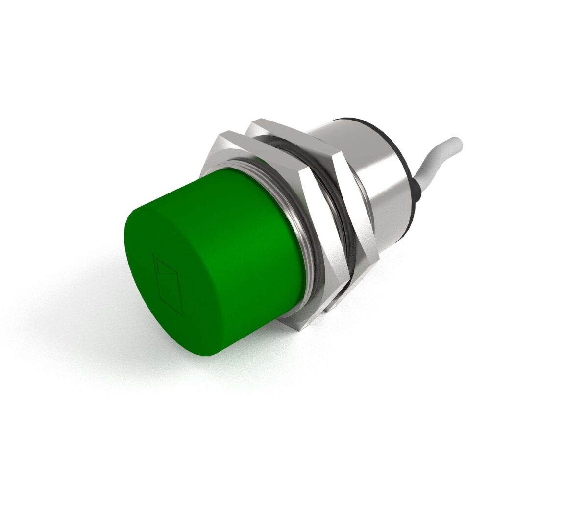
A PNP sensor sources current: when it detects a target it connects its output to +24 V. An NPN sensor sinks current: it connects its output to 0 V. The sensing element is identical in both. Only the output transistor differs, and that difference decides which PLC input card you can wire it to.
Quick reference
- PNP (sourcing) — load connects between the sensor output and 0 V (L−). Pairs with a sinking PLC input card.
- NPN (sinking) — load connects between the sensor output and +24 V (L+). Pairs with a sourcing PLC input card.
- PNP is the default across Europe and India; NPN dominates in Japanese and older Far-East machinery.
- Wire colours (IEC 60947-5-2): brown = L+, blue = L−, black = output, white = second output or NC.
- Getting it wrong does not usually destroy the sensor — the input simply never turns on.
What actually differs inside the sensor
Every DC three-wire proximity switch has the same three stages: an oscillator and demodulator that detect the target, a trigger stage that makes the on/off decision, and an output stage that drives the load. Only the third stage differs between PNP and NPN.
In a PNP output, the switching transistor sits between the positive rail and the output terminal. When the sensor operates, that transistor turns on and pushes +24 V out of the black wire. Current flows out of the sensor, through your load, and back to 0 V. This is why PNP is called a sourcing output.
In an NPN output, the switching transistor sits between the output terminal and the negative rail. When the sensor operates, the black wire is pulled down to 0 V. Your load must already be connected to +24 V, and current flows into the sensor. This is a sinking output.
The confusion that costs commissioning engineers hours is that the naming refers to the sensor, while PLC input cards are named for what they do. A sourcing sensor must feed a sinking input. They are always opposites.
PNP vs NPN at a glance
| PNP (sourcing) | NPN (sinking) | |
|---|---|---|
| Output when target detected | Switches to +24 V | Switches to 0 V |
| Load connected between | Output and 0 V | Output and +24 V |
| Current direction | Out of the sensor | Into the sensor |
| Required PLC input card | Sinking (common tied to 0 V) | Sourcing (common tied to +24 V) |
| Common in | Europe, India, most modern OEM machinery | Japan, Korea, legacy Far-East equipment |
| Short-to-earth behaviour | A chafed output cable can energise the load | A chafed output cable simply pulls the line low |
| Preferred for new builds | Yes — safer failure mode with earthed 0 V systems | Only when matching existing equipment |
Why PNP is the safer default
In the overwhelming majority of industrial panels the 0 V rail is bonded to earth. Consider what happens when the signal cable is crushed in a cable tray and the output conductor touches the machine frame.
With an NPN sensor the load is already sitting at +24 V and is waiting to be pulled down. An earth fault on the signal wire pulls it down exactly as the sensor would — the load energises. A conveyor can index, a cylinder can extend, and nothing in the control system knows a fault occurred.
With a PNP sensor the same earth fault simply shorts the output to 0 V. The load cannot energise. The input reads permanently off, which is noticed quickly and is the safer of the two failure states.
This is the practical reason IEC-aligned machine builders standardised on PNP, and it is why every Accent inductive proximity switch is offered in PNP as the default DC output, with NPN available where an existing installation demands it.
Reading the wiring before you connect
Three-wire DC sensors follow a colour convention that is consistent across reputable manufacturers:
- Brown — positive supply, +10 to +30 V DC on most units
- Blue — negative supply, 0 V
- Black — the switching output
- White — present on four-wire units: either a second, complementary output or the normally-closed contact
On an M12 connector the pin allocation is pin 1 brown, pin 2 white, pin 3 blue, pin 4 black. If you are staring at an unmarked sensor, a multimeter between brown and black with the supply connected will read close to supply voltage on an operated PNP unit and close to zero on an operated NPN unit.
Can you convert one to the other?
Not reliably, and not by rewiring. What you can do is adapt the input side:
- Change the PLC input card common. Most modern digital input modules let you choose sourcing or sinking by which rail you tie the group common to. This is the correct fix and costs nothing.
- Use an interposing relay. A 24 V DC relay coil driven by the sensor gives you a dry contact that suits any input. It adds a few milliseconds of delay and a wear item, so avoid it on high-speed counting duties — see our note on proximity switches in high-speed RPM counting.
- Fit a switching amplifier or control unit. Where the sensor is remote, in a hazardous area, or must drive an AC load, a standard control unit decouples the sensor from the load entirely.
What you must not do is add a pull-up or pull-down resistor and hope. That works on a bench and fails at temperature, because the output transistor’s leakage changes with junction temperature while your resistor does not.
NO, NC and why it is a separate question
PNP and NPN describe how the output switches. Normally open (NO) and normally closed (NC) describe when. A PNP NO sensor puts +24 V on the output when a target is present. A PNP NC sensor puts +24 V on the output when no target is present and removes it on detection.
For anything with a safety or presence-monitoring function, prefer NC. A broken cable or a failed sensor then produces the same signal as a missing target, so the fault is detected rather than masked. For genuinely fail-safe detection in hazardous areas the correct answer is a NAMUR proximity switch, which reports cable break and short circuit as distinct current levels — explained in our guide to how NAMUR sensors work.
Choosing for a real machine
Work through these in order:
- Look at the PLC first. Read the input card wiring diagram and see which rail the group common connects to. That single fact decides PNP or NPN, and everything else follows.
- Match the existing plant. If a line already runs on NPN, adding one PNP sensor creates a spares problem out of all proportion to the saving. Consistency beats theoretical preference.
- Confirm the load current. A typical DC three-wire output handles 100–200 mA. Contactor coils and lamp loads can exceed that; check the datasheet rather than assuming.
- Decide NO or NC on safety grounds, not on which one makes the ladder logic shorter.
- Check the supply. If the panel runs on 110 or 230 V AC and there is no 24 V rail, a two-wire AC sensor may be simpler than adding a power supply — but read our comparison of two, three and four-wire sensors before committing, because two-wire units bring leakage current problems of their own.
Frequently asked questions
Will an NPN sensor be damaged if I wire it to a sinking PLC input?
Usually not. The input simply never turns on, because both the sensor and the input are trying to pull the same line to 0 V and nothing sources current into it. The sensor is undamaged and works correctly once the input common is moved to +24 V. Damage only occurs if you connect the output directly across the supply.
How do I identify PNP or NPN on an unmarked sensor?
Power the sensor from 24 V DC with nothing connected to the black wire. Measure between black and blue (0 V) with a multimeter, then present a target. A PNP unit will swing to near +24 V. An NPN unit will stay near 0 V; measure between brown and black instead and you will see the voltage collapse when it operates.
Is PNP faster than NPN?
No. Switching speed is set by the oscillator and trigger stages, not the output transistor. Both types from the same product family carry the same rated switching frequency. Speed differences you see in practice come from the sensor size and sensing principle, not the output polarity.
Which should I specify for a new machine in India?
PNP, unless you are matching existing equipment. Indian machine building follows IEC practice, panel 0 V is normally earthed, and PNP gives the safer earth-fault behaviour. Availability of spares is also better.
Can one sensor have both PNP and NPN outputs?
Some four-wire units provide complementary NO and NC outputs of the same polarity, which is not the same thing. Genuine dual-polarity outputs exist but are uncommon and cost more than simply specifying the right sensor. For most applications, choosing correctly at order stage is cheaper.
Not sure which output your panel needs? Send us the PLC input card details and the target material. Accent Controls has been designing and manufacturing proximity switches in Mumbai since 1985, and our engineers will confirm the right part number before you order.